33
input value shall be 128-digit. It shall not be left in blank.
After completing all the setups please click save button, system goes back to the previous menu.
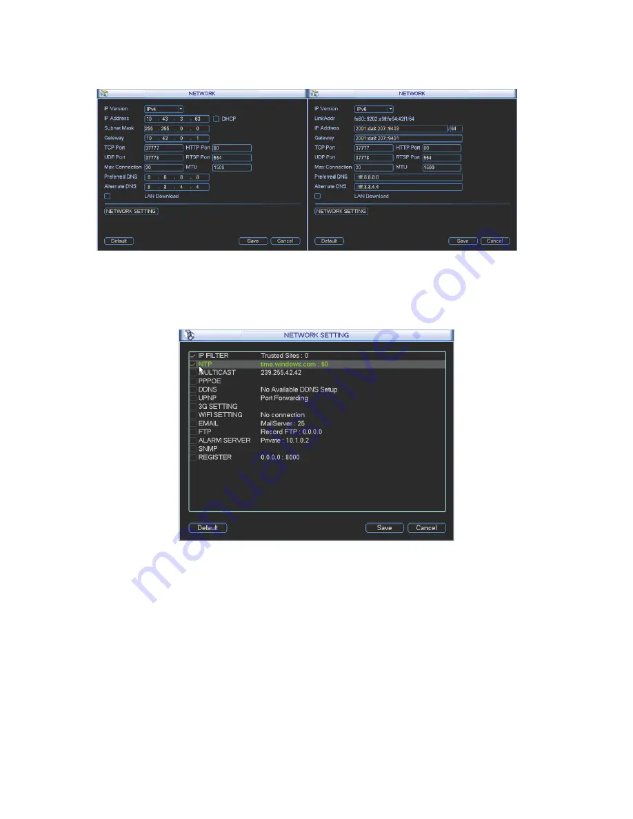
Figure 4-32
4.6.5.1 Network Setting
Network setting interface is shown as in Figure 4-33. Please draw a circle to enable
corresponding function and then double click current item to go to setup interface.
Figure 4-33
4.6.5.2 IP Filter
IP filter interface is shown as in Figure 4-34. You can add IP in the following list. The list supports
max 64 IP addresses. System supports valid address of IPv4 and IPv6.
Please note system
needs to check the validity of all IPv6 addresses.
After you enabled trusted sites function, only the IP listed below can access current NVR.
If you enable blocked sites function, the following listed IP addresses can not access current NVR.
z
Enable: Highlight the box here, you can check the trusted site function and blocked sites
function. You can not see these two modes if the Enable button is grey.
z
Type: You can select trusted site and blacklist from the dropdown list. You can view the IP
address on the following column.
Summary of Contents for Network Video Recorder
Page 1: ...Network Video Recorder Quick Start Guide Version 3 1 0 ...
Page 6: ...v z Please refer to the packing list in the box ...
Page 25: ...19 Figure 2 20 ...
Page 30: ...Network Video Recorder User s Manual V 3 1 0 ...
Page 85: ...48 Figure 4 54 Figure 4 55 Figure 4 56 ...
Page 142: ...105 signal which meets the senility standard that is previously set See Figure 6 42 ...
Page 175: ...138 Teclast Ti Cool 512M Teclast Ti Cool 1G Teclast Ti Cool 2G ...
Page 178: ...S oftware ...
Page 179: ...Cost effective HD IR Waterproof Fixed IP Camera Quick Start Guide Version 1 0 1 ...
Page 184: ...2 Figure 1 3 ...
Page 186: ...4 Figure 2 2 ...
Page 192: ...Cost effective HD IR Waterproof Fixed IP Camera User s Manual Version 1 0 2 ...
Page 201: ...5 Figure 2 2 Figure 2 3 ...
Page 203: ...7 Figure 3 2 ...
Page 209: ...IPC Web Operation Manual Version 3 0 0 ...
Page 236: ...25 Figure 4 11 4 2 6 SMTP e mail The SMTP interface is shown as in Figure 4 12 Figure 4 12 ...
Page 245: ...34 Figure 4 20 Figure 4 21 ...
Page 252: ...41 Figure 4 28 Figure 4 29 Figure 4 30 ...
Page 271: ...software NOT FOR SALE ...
Page 272: ...Clearview HD IR Waterproof Network Dome Camera Quick Start Guide Version 1 2 0 ...
Page 287: ...Clearview HD IR Waterproof Network Dome Camera User s Manual Version 4 0 1 ...
Page 312: ...software NOT FOR SALE ...


