TIP: When you run your camera wires, it is always a good idea to label each CAT5 camera
cable at the NVR end with each camera location to aid you later when you are installing your
cameras at the NVR.
•
Check local laws regarding installation & aiming of outside cameras, stay clear of AC electric wires
& fixtures, and be considerate of your neighbor’s privacy. Determine your camera locations, and
run the cables to each camera. Do not point cameras directly at light sources, or directly into the
rising or setting sun which may damage the camera’s sensors and will void warranty.
•
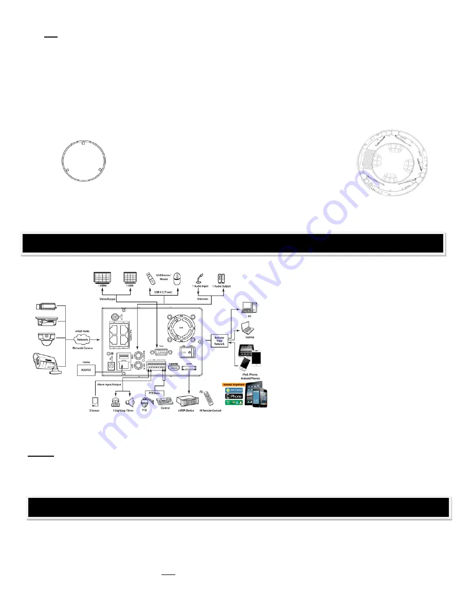
Use the included base mounting templates to mark the mounting screw holes.
Pre-drill the screw anchor holes with the 3/16” bit, and drill
the cable access holes with the 3/4” bit. Loosely attach each
camera in position with one or 2 screws, attach each
camera’s CAT 5 camera cable, and fish the camera wire
through to the NVR location.
DO NOT CUT CAMERA
WIRES
- this will void warranty. If the connections are exposed to weather,
seal with heat shrink tubing or self-adhesive sealing tape, then finish mounting the camera bases and
caulk/seal any outside holes.
Place the NVR and monitor within reach of
the provided 100 foot CAT 5 camera cables
and a wall plug AC power source (a battery
backup UPS is recommended). If you are
attaching a monitor using the HDMI output,
locate the unit so that is within reach of the
HDMI input on your TV or AV receiver.
At the NVR, attach the USB mouse and
your VGA monitor & power supply to AC
power. There are two power supplies in the
accessory box. One will power the NVR,
and the other will power the NVR’s internal
Power Over Ethernet
(or
POE
) switch -
which allows the cameras to draw power
from the CAT5 camera cable - each are marked and have different connectors to prevent connection mistakes.
Attach the NVR power supply, and the POE camera power supply, to the NVR.
NOTE:
On four channel units, all CAT 5 camera cables will connect to NVR. Eight channel systems will include
a
separate POE power switch
. This second POE switch will provide both video & power for the 4 additional
cameras. Connect this separate POE switch
directly
to the same router as your NVR,
not through another
switch,
to allow your NVR to correctly detect and install the cameras attached to the POE switch.
This is where the camera cable labeling done earlier comes in handy. Your new ClearView NVR makes
installation easy by providing camera power and video signal on one CAT 5 cable, and your NVR will assign
available channels
in the order you plug them into the ports
on the back of the NVR (or for 8 channel
systems, into the ports on the NVR and the provided separate POE switch).
NVR INSTALLATION
IP CAMERA INSTALLATION ON THE NVR
Summary of Contents for Network Video Recorder
Page 1: ...Network Video Recorder Quick Start Guide Version 3 1 0 ...
Page 6: ...v z Please refer to the packing list in the box ...
Page 25: ...19 Figure 2 20 ...
Page 30: ...Network Video Recorder User s Manual V 3 1 0 ...
Page 85: ...48 Figure 4 54 Figure 4 55 Figure 4 56 ...
Page 142: ...105 signal which meets the senility standard that is previously set See Figure 6 42 ...
Page 175: ...138 Teclast Ti Cool 512M Teclast Ti Cool 1G Teclast Ti Cool 2G ...
Page 178: ...S oftware ...
Page 179: ...Cost effective HD IR Waterproof Fixed IP Camera Quick Start Guide Version 1 0 1 ...
Page 184: ...2 Figure 1 3 ...
Page 186: ...4 Figure 2 2 ...
Page 192: ...Cost effective HD IR Waterproof Fixed IP Camera User s Manual Version 1 0 2 ...
Page 201: ...5 Figure 2 2 Figure 2 3 ...
Page 203: ...7 Figure 3 2 ...
Page 209: ...IPC Web Operation Manual Version 3 0 0 ...
Page 236: ...25 Figure 4 11 4 2 6 SMTP e mail The SMTP interface is shown as in Figure 4 12 Figure 4 12 ...
Page 245: ...34 Figure 4 20 Figure 4 21 ...
Page 252: ...41 Figure 4 28 Figure 4 29 Figure 4 30 ...
Page 271: ...software NOT FOR SALE ...
Page 272: ...Clearview HD IR Waterproof Network Dome Camera Quick Start Guide Version 1 2 0 ...
Page 287: ...Clearview HD IR Waterproof Network Dome Camera User s Manual Version 4 0 1 ...
Page 312: ...software NOT FOR SALE ...


