Determine which camera you want on Channel 1, and plug that camera’s CAT-5 cable into Channel 1 on the
NVR. Your NVR will detect the camera and – in a few seconds – your first camera’s images will appear on your
monitor screen. Repeat this process with each channel’s camera, plugging in each cannel’s CAT 5 cables
one
at a time
and
waiting about 30 seconds in between
connections.
To make sure your cameras are assigned correctly, wait for each camera’s image to appear before moving on
to the next camera. Once you are done plugging in the camera cables, you should be seeing video on the
monitor for each camera attached to the NVR. The IP addresses of the POE ports are 10.1.1.65 through
10.1.1.68 on the NVR. You can check each camera’s address, once you are signed in and after you finish NVR
Set Up (below), by selecting
Remote Device
to confirm camera connections.
On the NVR, use the mouse to
right-click
on the screen to bring
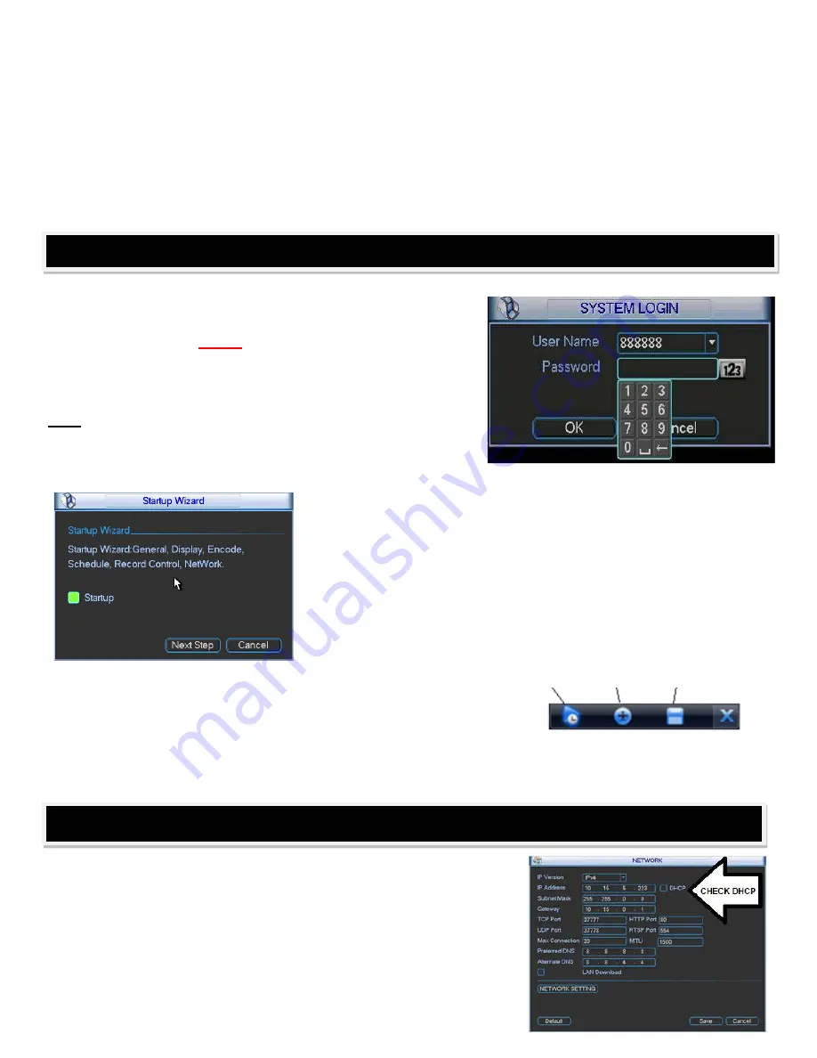
up the Log-In pop-up on-screen panel, and enter the
Login and
Password (both are “admin” as the factory default.)
For your
security, you should change the default log-in and password to
your own at this time.
Make sure to write down this information in
a secure, hidden place somewhere in case you forget it.
Note: For security reasons, entering the wrong log-in and/or
password 3 times will result in system alarm and 6 login
failures will result in account lock. If you are locked out,
please call tech support.
Once you log in, the system will begin the
Startup Wizard
, and guide
you through the unit’s initial set up. During camera setup, the NVR
assigned each camera to the correct channel as you plugged them in.
Once finished you will see your cameras in live view on screen
automatically, your video will be automatically be recorded to the hard
drive, and all video channels will be ready to review from this screen.
To review recorded video
, use the mouse to move your cursor over
any live camera video, and the menu below will appear over the
selected channel’s video screen:
Playback Zoom Record to USB
Playback
allows you to replay the last 5-60 minutes of video from that
channel.
Zoom
allows an electronic zoom on the channel’s video, by
dragging the cursor to select the area to be enlarged.
Record to USB
allows up to 60 minutes of the selected channel’s recorded video to be copied to a USB device (thumb drive,
etc.) The “
X
” at the left end of the bar closes this menu bar.
Congratulations – you have successfully installed your ClearView NVR!
Now that your ClearView video system is up & running, you can
connect it to your network to view and work with from a remote PC or
Apple Mac computer on your network and online.
To start, plug in a Cat 5 network cable to the RJ-45 network port on the
rear of the NVR, and then into an available port on your network’s
router. Then, right click on the NVR screen using the mouse and log
into the NVR, and from the
Main Menu
choose
SETTING
, then
NETWORK
, and
check the DHCP button
on the second line of the
Network window. Your our router will assign & display your IP address
NETWORK & ONLINE SETUP
NVR SET-UP
Summary of Contents for Network Video Recorder
Page 1: ...Network Video Recorder Quick Start Guide Version 3 1 0 ...
Page 6: ...v z Please refer to the packing list in the box ...
Page 25: ...19 Figure 2 20 ...
Page 30: ...Network Video Recorder User s Manual V 3 1 0 ...
Page 85: ...48 Figure 4 54 Figure 4 55 Figure 4 56 ...
Page 142: ...105 signal which meets the senility standard that is previously set See Figure 6 42 ...
Page 175: ...138 Teclast Ti Cool 512M Teclast Ti Cool 1G Teclast Ti Cool 2G ...
Page 178: ...S oftware ...
Page 179: ...Cost effective HD IR Waterproof Fixed IP Camera Quick Start Guide Version 1 0 1 ...
Page 184: ...2 Figure 1 3 ...
Page 186: ...4 Figure 2 2 ...
Page 192: ...Cost effective HD IR Waterproof Fixed IP Camera User s Manual Version 1 0 2 ...
Page 201: ...5 Figure 2 2 Figure 2 3 ...
Page 203: ...7 Figure 3 2 ...
Page 209: ...IPC Web Operation Manual Version 3 0 0 ...
Page 236: ...25 Figure 4 11 4 2 6 SMTP e mail The SMTP interface is shown as in Figure 4 12 Figure 4 12 ...
Page 245: ...34 Figure 4 20 Figure 4 21 ...
Page 252: ...41 Figure 4 28 Figure 4 29 Figure 4 30 ...
Page 271: ...software NOT FOR SALE ...
Page 272: ...Clearview HD IR Waterproof Network Dome Camera Quick Start Guide Version 1 2 0 ...
Page 287: ...Clearview HD IR Waterproof Network Dome Camera User s Manual Version 4 0 1 ...
Page 312: ...software NOT FOR SALE ...


