O
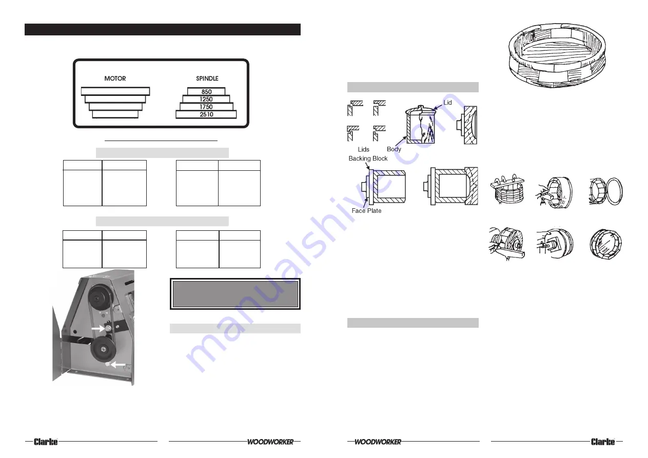
SPINDLE SPEEDS
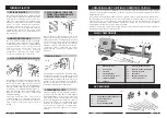
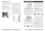
A chart showing spindle speeds and recommended turning speeds is mounted on the Head cowl
and for convenience, is duplicated as follows:
CAUTION : MAKE SURE THE POWER CORD IS
REMOVED FROM THE OUTLET BEFORE
ATTEMPTING TO CHANGE THE BELT POSITION.
Changing speeds
1.
Undo the two screws securing the Pulley
Access Panel.
2.
Slacken the two Motor securing bolts -
arrowed in Fig. 3.
3.
Pull down on the Belt Tension Lever to
remove belt tension.
4.
Move belt to appropriate pulley.
5.
Pull up on Belt Tension Lever to tension belt.
It should be firm - 1/2” total movement at
the middle of the run.
6.
Retighten Motor securing bolts and replace
Pulley Access Cover.
8
SPINDLE SPEEDS
Fig. 3
RECOMMENDED GENERAL SPEEDS
SPINDLE TURNING
SQUARE
LENGTH
ROUGHING
FINISHING
1” (25mm)
12” (305mm)
1750
2510
2” (50mm)
16” (406mm)
1250
2510
3” (75mm)
20” (508mm)
850
2510
4” (100mm)
20” (508mm)
850
2510
DIAMETER
THICKNESS
ROUGHING
FINISHING
9” (228mm)
4” (100mm)Max.
850
2510
8” (205mm)
4” (100mm)Max.
1250
2510
6” (150mm)
4” (100mm)Max.
1750
2510
FACE PLATE TURNING
Fig.3 shows the belt positioned on the second
step from the outside edge of the pulley. This
produces a spindle speed of 1250 RPM. (Refer
to the chart above).
If you wish to run at a higher speed, say 2510
RPM, you must shift the belt inwards, 2 steps.
the ball is constantly shifted, never more than
1/8 turn and always with a definite pattern. Since
turning between centres makes the work a
perfect sphere across the grain, the ball must
be mounted in the chuck so that the first
scraping cuts will round it up in the opposite
direction .
6. TURNED BOXES
To make the 12-piece bowl, a board about
22x76x760mm, is cut into pieces about 65mm
long, the saw blade being tilted 15° and the
board being turned alternatively face up and
face down to make the successive cuts. These
12 pieces glued together and clamped by
wrapping the assembly with wire. When dry the
rim thus formed is glued to a temporary circular
backing which is mounted on the large
faceplate.
Turned boxes involve deep recessing together
with a special system of working the lid and body
of the box together as one unit. The inside of
the lid is turned first. Next, the inside of the body
is turned. A careful check must be made when
turning the body portion so that the lid will be a
tight press fit. The lid is then pressed on to the
body and the outer circumference and face of
the lid, together with the outer circumference
of the body, are turned all at one time. This
insures accurate matching of the two pieces.
After the work is complete, the tight fit of the lid
can be relieved by sanding the lip of the body.
7. SEGMENTED TURNINGS
Segmented turnings and boxes can be
extremely attractive and this method of
preparing wood stock is more economical than
the use of a large stock piece.
For some types of work, segmenting is the only
practical method because a block (if
obtainable), would be so large that it would be
very likely to warp.
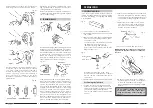
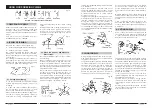
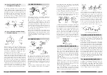
The bowl illustrated in fig. 51 requires 12 segment
pieces for the sides. Bowls can be worked with
6 or 8 pieces if desired.
A recess of the largest possible diameter, and
about 22mm deep, is turned in the open end of
the rim. The rim is removed from the lathe, and
stock for the bottom is mounted in its place on
a second faceplate. This is turned to size and a
rim about 3mm deep is turned to exactly fit the
recess prepared in the rim. The rim is then fitted
over the bottom and glued, making a drum
shape with a faceplate at each end. This drum
is cut completely in two, at a point about 22mm
above the bottom, completing the cut with a
hand saw. Both parts of the cut surface are
faced off square and smooth, then reglued
together, breaking the joints exactly half and
half. The cutting and regluing process is
repeated with a section about 32mm wide.
After this, the temporary backing block is cut
off, leaving the bowl as shown in the final
illustration. From this point on the work is simply
a matter of turning down the bowl to any desired
shape.
25
Fig. 52
Fig. 51
Fig. 50


