


O
10
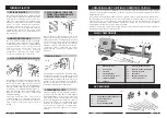
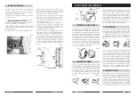
Fig. 9
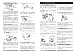
2. FACEPLATE TURNING
Turning which cannot be worked through
centres, must be mounted on a faceplate, or
other work-holding device. (Some jobs may
require the use of special chucks).
To attach the face plate, first remove the Drive
Centreas follows:
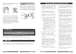
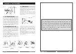
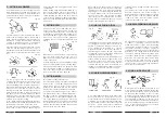
Removing the Drive Centre
Hold the spindle with the spanner provided, on
the flats machined on the spindle.
Using a suitable spanner on the Drive centre, turn
it anticlockwise whilst holding the drive centre
steady - See Fig 8.
The Face Plate is removed in a similasr manner
All face plate work is done by scraping. Any
attempt to use a cutting technique on edge
grain, will result in hogging or gouging, which
may tear the tool out of your hands.
For Faceplate turning, the work (suitably
trimmed so that it is as near to its final
dimension as possible), should be firmly
mounted on to the faceplate, using screws as
appropriate (see fig. 9).
The complete assembly is then screwed on to
the headstock spindle, and tightened
securely, by holding the faceplate, and
turning the spindle nut using a spanner, to lock
it up against the faceplate boss.
The screws used in securing the work to the
face plate, must not be of sufficient length as
to interfere with the tool at the final dimension.
It may be necessary to screw the work to a
backing piece, depending upon design, or
where screws are not permissible at all, the
work may be glued to a backing piece, fitting
a piece of paper at the joint, which will allow
for later separation without damaging the
wood.
Fig. 8
FANCY FACE PLATE TURNINGS
After making a recess at least 1/2 the way
through the workpiece, and finishing this on the
inside, remove the workpiece from the lathe.
Now mount a short length of soft wood stock on
the screw centre and turn this down to form a
dowel that will be a tight press (not driving) fit
inside the recessed end of the cylinder. Mount
the cylinder on this wooden chuck, and recess
the unworked end deep enough to form a
perfect hole through the entire cylinder.
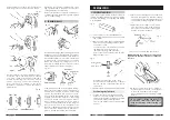
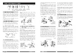
3. RECHUCKING
Rechucking is the general term used to describe
any additional work mounting that is necessary
to complete a turning project. The method of
working cylinders, and the use of a plug chuck
as already described are typical examples.
Another good example is the rechucking of a
bowl.
1.
PREPARING A PLUG CHECK
A plug check is an auxiliary wood chuck
mounted onto a faceplate. The chuck can be
any size diameter, should be about 65mm thick
for stability and should be provided with a 20mm
hold in the centre for receiving a tenon turned
at the end of the workpiece. Once made, such
chucks are permanent useful fixtures for turning
balls, goblets etc. In use, the wood stock for
turning is turned between centres to produce a
tenon at one end which will be a driving fit in
the hole of the chuck. When mounted in the
chuck, the workpiece is substantially supported
for any faceplate type of turning.
2.
TURNING CYLINDERS
Stock for cylinders should be mounted on the
screw centre or a small faceplate. The tailstock
can be brought up to support the work while
the circumference is being turned and finished.
Afterwards, the tailstock is backed off and the
outer end of the cylinder is recessed, using
methods already described for making deep
presses.
The work is mounted on a wood backing block
secured to the large faceplate, and is turned in
the usual manner, except for the back side
(which is against the mounting block). It is then
removed from the mounting block. An auxiliary
chuck of soft wood is now made in the same
manner as that for the cylinder chuck. This
chuck must have a turned recess properly sized
to accommodate the rim of the bowl in a tight
press fit. When the bowl is mounted in this chuck,
the bottom can be cleaned off and slightly
recessed to complete the desired contours.
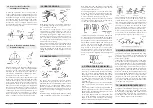
4. TURNING A RING
One method of turning a ring requires a spindle
chuck. The work stock is first mounted to a
backing block held by the large faceplate, and
is turned to shape on the outer side. The inside
diameter of the ring is also shaped, all the way
through to the backing block. The work is then
removed from the backing block. A spindle
chuck is now prepared so that it will be a tight
press fit inside the ring, and the ring is reversed
23
Fig. 46
Fig. 45
Fig. 44
Fig. 43