O
1. TYPES OF PLASTICS
There are two general groups of plastics. The first
includes all phenol plastics moulded under heat
and pressure. Bakelite and For mica are
examples. In the second are all catalyst setting
plastics of various bases sold under such trade
names as Lucite, Catalin, Cast Bakelite,
Marblette, Tenite and Trafford. Those in the
second group are most generally used for
craftwork. They are easy to turn, being a little
harder than wood but much softer than any of
the soft metals.
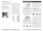
2. MOUNTING THE WORK
The most useful mounting device is the 4-jaw
(metal lathe) chuck. When this is not available,
cylinders can be mounted on a slightly tapered
wooden mandrel. Rods can be mounted
between centres, using either the wood
mounting centres or metal mounting
arrangements. When the spur centre is used,
slots should be sawed across the work.
3. USE OF WOOD TURNING CHISELS
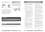
4. USE OF FORMED TOOLS FOR
PRODUCTION BEADING AND
SIMILAR OPERATIONS
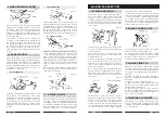
Standard wood turning chisels are excellent for
turning plastics by means of scraping methods.
The tool rest should be slightly below centre and
the chisel handle should be held a little higher
than the cutting edge to give a negative rake.
Scraping tools should be kept to a minimum. A
large contact area, such as the full edge of the
spear-point chisel, will cause chatter and
probable chipping.
Properly worked, the chip comes off in a
continuous ribbon. In cold weather, plastic may
become brittle and should be tempered in
warm water for about ten minutes before
turning.
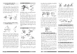
When a number of identical pieces are to be
produced, all having a distinctive sur face
pattern, preformed tools will speed the work and
assure uniformity. Patterns like those illustrated
can be created by grinding thin gauge
aluminium strips. A holder, like the one shown,
can then be used to support any one of your
prepared strips and guide it against the
workpiece.
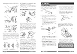
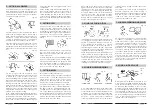
5. TURNING BALLS
Plastic balls are rough turned in the usual manner
and then brought to perfect roundness by using
a tube tool. The tube should be slightly less in
diameter than the finished size of the ball. It can
be brass or steel, ground square across the end.
The tool is used with or without a rest, and is
worked by swinging it from side to side.
6. POLISHING PLASTICS
Start with sanding. First use 150-grit dry paper to
remove tool marks, than finish off with 150-grit
and 400-grit papers, in succession, used wet.
Press lightly to avoid overheating and marring
the work. Buffing gives the final polish, using the
polishing compounds commonly supplied for this
purpose. Do not press too hard or hold wheel
at one spot too long, keep moving around,
otherwise the plastic might become heat
marked.
26
Fig. 55
Fig.54
Fig. 53
TURNING PLASTICS
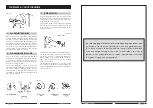
Your wood lathe is shipped complete in one carton and is fully assembled at the factory, with the
exception of the Belt Tensioning Lever. Screw this into the socket to the left of, and directly below,
the ON/OFF switches.
If any parts are missing or damaged in any way, please contact your Clarke dealer immediately.
Ensure the lathe is secured firmly to a firm level surface...a sturdy workbench for example, or, if
necessary, a piece of 1/2” ply may be used, and this in turn should be clamped to a strong work
surface when the lathe is in use. The lathe may then be moved to a more convenient location for
storage purposes. This is handy if workspace is limited.
If a piece of ply is used, ensure the mounting screws are countersunk into the underside of the ply, so
that the bearing surface is completely flat.
UNPACKING AND CHECKING CONTENTS OF CARTON
Fig. 1
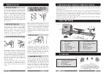
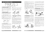
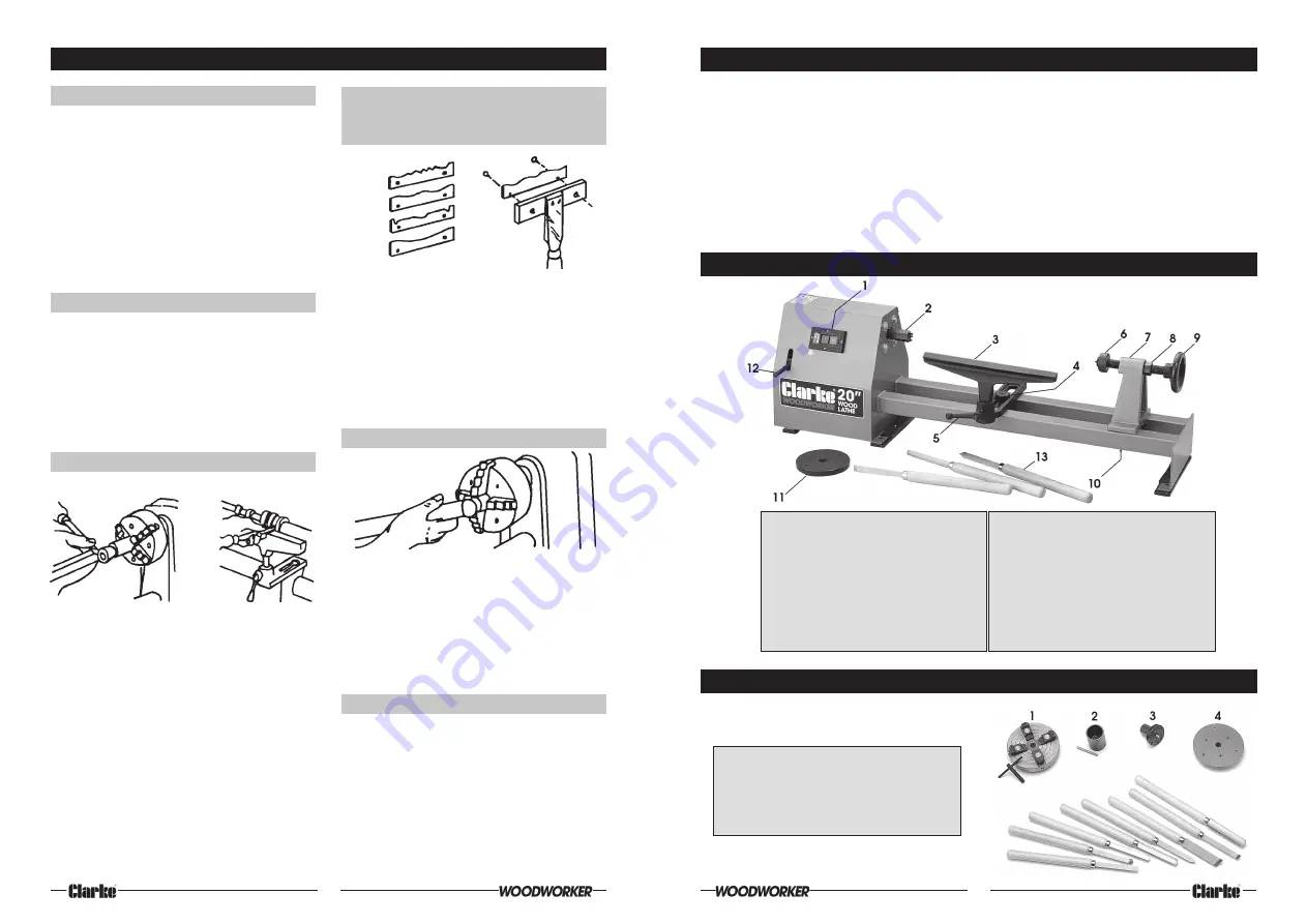
MAIN COMPONENTS
Fig. 2
7
ACCESSORIES
1.
4-Jaw Independent Lathe Chuck
2.
Cup Turning Chuck
3.
Screw Chuck
4
Face Plate Right Hand
1.
ON/OFF switches
2.
Drive Centre
3.
Tool Rest
4
Tool Rest Holder
5.
Tool Rest Locking Lever
6.
Tailstock Spindle
7.
Tailstock
8.
Tailstock Spindle Locknut
9.
Tailstock Advancing Handle
10.
Tailstock Locknut
11.
Face Plate
12.
Belp Tensioning Lever
13.
3-Piece Chisel Set


