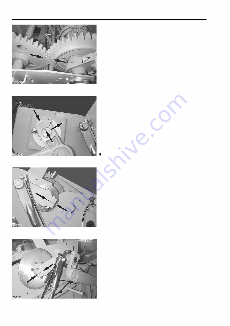
Basic settings for the drives
3
5
6
1.6 / 2
3. The marking on the spur gear of the countershaft
and the grease nipple on the spur gear of the
knotter shaft must be aligned with each other.
Note:
Remove the protective plates from over the
spur gears.
(Fig. 3)
4. Crank arms for the feed rake control
The markings on the countershaft must align with
the slots on the crank arms on both sides. The
second marking on the countershaft will then be
towards the rear.
(Fig. 4)
5. Crankshaft for the needle drawbars
The markings on the knotter shaft must align with
the slots on the crank arms - on both sides.
(Fig. 5 and 6)
QUADRANT 2 2 00 / 2 2 00 RC


