background image

Basic settings for the twine wrap device 

13 

-t:::::===============ii:1§:�1 

�=cc======::::i===-

M"LlP 

-.....;_11 

200741 

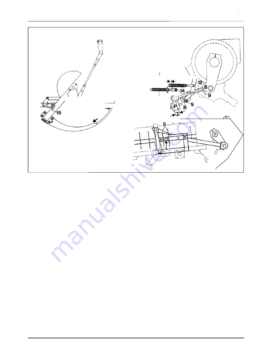
Ram stop 

The ram stop is built on next to the main gearbox. 

It protects the needles against damage, should these 

come to a stop in the bale chamber. If this event 

occurs, the shear bolt on the main gearbox shears 

off. 
Setting the ram stop: 

PLEASE NOTE! 

The rubber pressure springs (P) 

must be set to the dimension (Z)  5 6  ± 1 mm. 

1 .  Release the tying cycle and turn the flywheel 

by hand 

in the direction of the arrow until the 

needles are in the bale chamber. 

2.  Turn the flywheel against the direction of the 

machine until the crank arms (8)  have just passed 

the ram stops ( 9). The ram stops give way 

against the pressure of the crank arms. 

(Fig. 18) 

QUADRANT  2 2 00 /  2 2 00 RC 

10 

1.7 /  9 

Summary of Contents for QUADRANT 2200

Page 1: ...REPAIR MANUAL CLAAS QUADRANT 2200 QUADRANT2200 ROTO CUT ...

Page 2: ...298 170 0 QUADRANT 2200 2200 ROTO CUT GB 06 01 100 BEV Find manuals at http best manuals com search s CLA 2981710 ...

Page 3: ...Notes __ 2 Drives _______ 3 Pick up __ 4 Baling unit _______ 5 Twine wrap device __ 6 Assembly _______ B Axles __ 9 Hydraulics and Electrics _______ 1O Central lubrication system Find manuals at http best manuals com search s CLA 2981710 ...

Page 4: ...1 General Notes Find manuals at http best manuals com search s CLA 2981710 ...

Page 5: ...antities 1 5 1 BASIC SETTINGS FOR THE DRIVES Adjusting the drives to the markings 1 6 1 BASIC SETTINGS FOR THE TWINE WRAP DEVICE Setting up the knotter shaft and needles 1 7 1 Checking the setting of the needles to the piston 1 7 4 Opportunities for control checks in the bale chamber 1 7 5 Needle yoke brake 1 7 6 Knotter shaft brake 1 7 6 Adjusting the springs for the clamping plates 1 7 7 Adjusti...

Page 6: ... CLAAS KGaA mbH Customer service The CLAAS REPAIR M ANUAL is divided into main sections and subsections The first digit of the number at the foot of each page shows the main section the number behind the decimal point refers to the sub section and the number which follows the slash line refers to the page number In each sub section the pictures and pages are numbered consecutively from 1 onwards D...

Page 7: ...rring operational steps and notes in the pictures and figures Dismantle Grease Prevent material Remove damage I Disassemble Oil I Special tools Assemble Setting up Drainage Drainage outlet i Installation Visual check Filling up Fitting Control Filler opening BJ M arking I Unlock Overflow Secure Balancing Liquid locking ljil Venting Glueing Sealing Limited Underpin re usability Support Prop up Repl...

Page 8: ...RANT 2 2 00 2 2 00RC General notes on repair The full load capacity of these bolts is reached after 2 4hours at a temperature of 2 0 C The time to achieve full load capacity can be shortened by heating e g at 7 0 C for 15 minutes 7 Liquid bolt locking e g Delo M L 18 7 Only use bolt locking liquid where specified by the manufacturer Correct use M etal connections which are to be fitted using bolt ...

Page 9: ...may turn but it must not be possible to move it ax ially Final assembly Fit the pre assembled pipe into the properly oiled screw socket tighten the connecting nut until the increasing resistance can be felt and then turn it through a further 1 2 turn Re assembly After each subsequent loosening of the cutting ring connection tighten the connecting nut again but this time without using additional fo...

Page 10: ... 2 5 10 0 7 2 0 0 8 7 0 0 hex agonal nuts M2 4 640 0 9 00 0 108 0 0 DIN 9 3 4 M2 7 98 0 0 1400 0 165 0 0 M3 0 12 60 0 18 00 0 2 160 0 Dimensions Fine M etric Thread M8 x 1 2 5 3 5 42 M10x 1 2 5 48 67 8 0 M12 x 1 2 5 88 12 5 15 0 hex agonal bolts M12 x 1 5 8 2 113 140 DIN 9 60 M14x 1 5 13 5 19 0 2 2 5 DIN 9 61 M16x 1 5 2 10 2 9 0 3 45 M18 x 1 5 3 00 415 5 05 M2 0x 1 5 415 58 5 7 00 hex agonal nuts ...

Page 11: ...49 M8 x 1 7 2 Nm M10x 1 11 4 Nm M12 x 1 5 15 5 Nm M14x 1 5 2 3 8 Nm M16x 1 5 2 9 1o Nm M18 x 1 5 38 13 Nm M2 0x 1 5 46 15 Nm M2 2 x 1 5 67 22 Nm M2 4x 1 5 8 6 29 Nm M2 6x 1 5 103 34 Nm M2 7 x 2 103 34 Nm M3 0x 2 17 0 57 Nm M3 3 x 2 2 00 67 Nm M3 6x 2 2 45 82 Nm M38 x 2 2 45 82 Nm M3 9 x 2 3 10 1o3 Nm M42 x 2 38 0 127 Nm M45 x 2 440 147 Nm 1 4 2 QUADRANT 2 2 00 2 2 00RC ...

Page 12: ... B API GL 4 9 0 ca 2 51 Gearbox knotter drive ca 1 2 51 Transfer gearbox rotor feed rake drive ca 5 0 I M ulti purpose gearboxoil SAE 9 0 Upper gearbox rotor drive M IL L 2 105 B API GL 5 9 0 ca 0 81 Hydraulic system M ultigrade hydraulic oil ca 17 0 I Shell Hydrol HV 46 Tellus T 46 DonaxTM Fuchs Renolin D 46HV Wintershall HVG 46 Compressor M ultigrade engine oil ca 17 5 ml SAE 15 W 40 QUADRANT 2 ...

Page 13: ...eedle to the piston 2 Set the baling ram to the front dead centre so that the crank arms and the piston bars lie parallel nex t to each other The hole B on the left crank arm pivot must then be on a level with the cap nut 1 1 In this position all the markings on the corresponding drives must align with each other and align with the shafts Fig 1 and 2 QUADRANT 2 2 00 2 2 00RC 2 203357 Basic setting...

Page 14: ...ve plates from over the spur gears Fig 3 4 Crank arms for the feed rake control The markings on the countershaft must align with the slots on the crank arms on both sides The second marking on the countershaft will then be towards the rear Fig 4 5 Crankshaft for the needle drawbars The markings on the knotter shaft must align with the slots on the crank arms on both sides Fig 5 and 6 QUADRANT 2 2 ...

Page 15: ...e of the tine tube to the centre of the bolt head must be 3 28 15 mm Fig 1 and 8 This setting can be corrected by moving the position of the drive shaft W between the main gearboxand the transfer gearbox Fig 1 and 9 Procedure Remove the retaining ring S Completely remove the drive shaft W Set the distance X between the upper edge of the tine tube and the centre of the bolt heads to 3 28_15 mm Fig ...

Page 16: ... the sections at the two ends are different turn the shaft until the correct installation position has been found To do this dimension X between the upper edge of the tine tube and the centre of the bolt heads can be changed by 15 mm Finally replace the retaining ring S Check the set distance 3 28 15 mm once again Fig 8 10and 11 QUADRANT 2200 2200 RC ...

Page 17: ...he lateral stops of the needles on the knotter frame Set up the needles 1 on the needle brackets align to the centre of the needle slot and screw tight The bolt torque of the hex agonal bolts 2 M 10 45 Nm Trigger the tying cycle using the control terminal or mechanically by pushing forward the cam N at the control lever S Fig 1 and 2 QUADRANT 2 2 00 2 2 00RC Basic settings for the twine wrap devic...

Page 18: ...terally as required Fig 1 and 3 Adjusting the height of the needles Release the tying cycle Turn the flywheel by hand in the direction of the arrow until the needle pulleys are over the corners of the clamping plates 5 Check the distance C between the lower edge of the needle to the upper edge of the clamping plates with the gauge E It must be 5_ 3 mm see detail V Loosen the three bolts 6 and then...

Page 19: ... the top dead centre position In this position the needle drawbars 3 and the crank arms 4 should lie parallel to and over one another Check the distance B from the rear edge of the clamping plate 5 to the centre of the needle pulleys with the gauge E This distance must be from 9 5 to 100mm see detail W If necessary adjust the length of the needle drawbars in order to correct the setting Fig 1 and ...

Page 20: ... Turn the piston towards the rear by turning the flywheel by hand in the direction of the arrow until the red gauge L on the baling ram on the left side of the machine is situated between the brace S and the bar H The markings M on the needles must then be at point 11 at the level of the guide A Fig 6 7 and 8 QUADRANT 2 2 00 2 2 00RC ...

Page 21: ...e tying cycle Turn the piston towards the rear by turning the flywheel by hand in the direction of the arrow until the markings M on the needles are at point 11 at the level of the guide A Lock the knotter drive shaft by pushing a mandrel into the interlock between the cogwheels Then remove the articulated shaft Turn the piston towards the rear by turning the flywheel by hand in the direction of t...

Page 22: ...sion X is 2 5 mm Fig 10 Knotter shaft brake The knotter shaft brake B prevents a whip effect following the return movement of the needles Fig 11 Setting the knotter shaft brake Set the springs on the knotter shaft brake B so that the spring length dimension X is 2 5 mm Fig 11 and 12 PLEASE NOTE The knotter shaft brake is set correctly if there is still some play available when the needles are rest...

Page 23: ...e the spring for the clamping plate After making the settings tension the spring in accordance with Fig 14 dimension X The play in the knotter pinion can be checked at the knotter hooks There must be no play in the knotter drive pinion and it must rest freely against the knotter disc To make the settings loosen the four fastening bolts on the knotter frame Use a pointed object screwdriver or simil...

Page 24: ...ne fingers The rod linkages 2 must be set up so that the distance from the centre of the ball head dimension B is about 2 00mm With twine fingers 1 at the end position the point must lie on the knotter plate 4 If necessary compensate for the ax ial play in the twine finger at C using shims In this position the distance from the twine fingers 1 to the tip of the twine guide 3 dimension A must be 0 ...

Page 25: ...he main gearboxshears off Setting the ram stop PLEASE NOTE The rubber pressure springs P must be set to the dimension Z 5 6 1 mm 1 Release the tying cycle and turn the flywheel by hand in the direction of the arrow until the needles are in the bale chamber 2 Turn the flywheel against the direction of the machine until the crank arms 8 have just passed the ram stops 9 The ram stops give way against...

Page 26: ...l of the guide A This control point can be seen from the bottom front in the twine box es through the holes provided for this purpose In this position the pulley R on the lever 12 must touch the control curve at S If necessary correct the setting by adjusting the clevis head G on the drawbar 13 To make the settings the needles must be turned again into the bale chamber This is necessary in order t...

Page 27: ...2 Drives ...

Page 28: ...ank arm bearing 2 2 2 Disassembling the knotter drive 2 2 6 Breakdown of the knotter drive 2 2 8 Assembling the knotter drive 2 2 9 Sealing the housing cover for the output shaft 2 2 12 Disassembling the main drive 2 2 14 Breakdown of the main drive 2 2 16 Assembling the main drive 2 2 17 Sealing the housing cover 2 2 2 0 Sealing the drive shaft for the spur gearing 2 2 2 1 Checking the angular pl...

Page 29: ...DRIVE Removing the control shaft 2 5 1 Breakdown of the control shaft 2 5 3 Fitting the control shaft 2 5 4 Completely removing the knotter shaft 2 5 6 Breakdown of the knotter shaft 2 5 10 Fitting the knotter shaft 2 5 11 Removing and dismantling the clutch for the knotter shaft 2 5 16 Breakdown of the clutch for the knotter shaft 2 5 17 Assembling and fitting the clutch for the knotter shaft 2 5...

Page 30: ...shaft Fig 1 Unscrew the bolts S and lift off the friction clutch R from the flange plate PLEASE NOTE The bolts were inserted and set with bolt locking liquid and therefore fit tightly Fig 2 Dismantling the friction clutch Unwind all the nuts M to the same ex tent until the adjusting ring 2 is free Carefully lever out the adjusting ring 2 from the clutch housing and lift out the spring assembly 3 F...

Page 31: ...This as a preview PDF file from best manuals com Download full PDF manual at best manuals com ...

Reviews: