41
TS9000/TS9050 TouchStar Systems User Manual
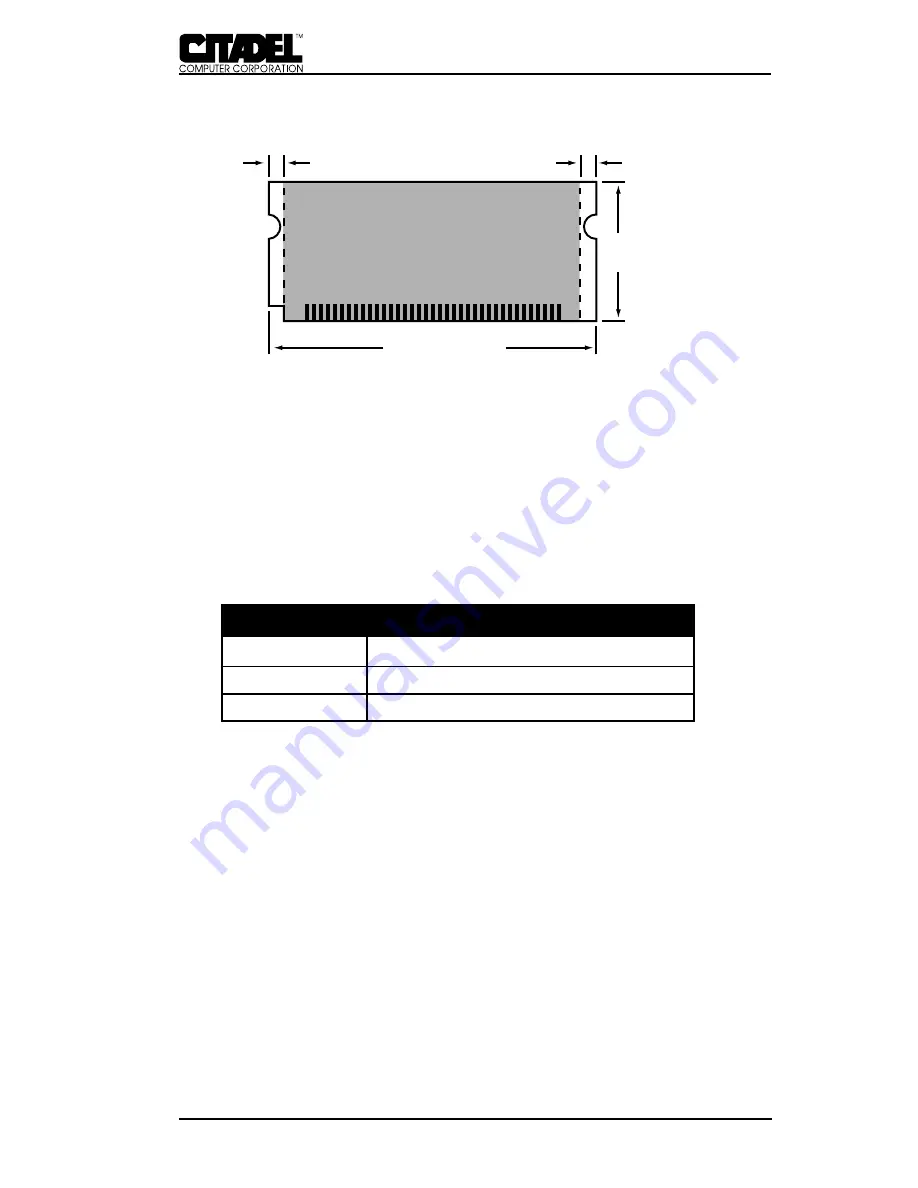
0.085" Clear
1.00" Typ.
2.350" Typ.
Component
Area
0.085" Clear
Figure 18. SODIMM Guide Clearance Requirements
CMOS RAM
On-board feature configuration information is stored in AT-style
CMOS random access memory (RAM). The TouchStar integrates
128 bytes of CMOS RAM and real time clock (RTC) into the
main system controller. The system’s CMOS RAM is accessed
via I/O locations 0070
H
- 0071
H
. Table 9 shows the configuration
of the system’s available memory.
TABLE 10 - CMOS RAM MEMORY ALLOCATION
Location
Description
0 -13
Real-time Clock (RTC) Functions
14 - 127
General Low-Power Static RAM
Multiple memory locations in the TouchStar are reserved for
storing BIOS-dependent configuration information. To access
CMOS RAM, the index address (0 to 7F
H
) is output to port 70
H
,
and the data is then read or written at port 71
H
. Interrupts
should be inhibited while the entire port 70
H
/71
H
sequence is
completed. Alternatively, the port sequence can occur during an
interrupt service routine before re-enabling interrupts. If these
precautions are not observed, an interrupt service routine could
potentially intervene between the output to port 70
H
and the
subsequent I/O to port 71
H
, overwriting the port 70
H
value.
Flash Drives
The TouchStar contains 2MB or 4MB of Flash memory config-
ured as a solid-state drive. The on-board flash array is sup-
ported as a bootable, read-writable drive. Once the Flash Array
SYSTEM REFERENCE - B


