


3-35
Cisco UCS S3260 Storage Server Chassis Installation and Service Guide
Chapter 3 Maintaining the System
Installing or Replacing System Components
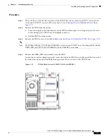
Step 3
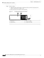
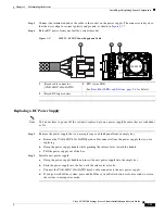
Connect the terminated end of the cable to the socket on the power supply. The connector is keyed so
that the wires align for correct polarity and ground, as shown in
.
Step 4
Return DC power from your facility’s circuit breaker.
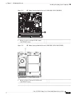
Figure 3-17
1050 W, –48 VDC Power Supply and Cable
Replacing a DC Power Supply
Note
You do not have to power off the system to replace up to one power supply because they are redundant
as 3+1.
Step 1
Remove the power supply that you are replacing or a blank panel from an empty bay:
a.
Remove the CAB-48DC-40A-8AWG keyed cable connector from the power supply that you are
replacing.
b.
Grasp the power supply handle while pinching the release lever toward the handle.
c.
Pull the power supply out of the bay.
Step 2
Install a new power supply:
a.
Grasp the power supply handle and insert the new power supply into the empty bay.
b.
Push the power supply into the bay until the release lever locks.
c.
Connect the CAB-48DC-40A-8AWG keyed cable connector to the new power supply.
d.
If you powered off the system, press and hold the system Power button for four seconds to return
the system to main power mode.
1
Keyed cable connector
(CAB-48DC-40A-8AWG)
3
PSU status LED
See
Rear-Panel LEDs and Buttons, page 3-4
for details.
2
Keyed DC input socket
305145
1
2
3
1050W DC
+DC
- DC


