background image


1-4

Cisco UCS S3260 Storage Server Chassis Installation and Service Guide


Chapter 1      Overview

Replaceable Component Locations

Replaceable Component Locations

This section contains the following topics:

Replaceable Components Inside the Main Chassis, page 1-4

Components Inside the C3X60 Server Node, page 1-6

Components Inside the I/O Expander, page 1-6

Components Inside the System I/O Controller, page 1-7

Replaceable Components Inside the Main Chassis

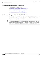
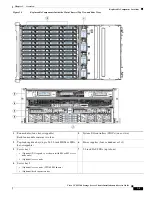
This section shows the locations of the replaceable components that are inside the main chassis. Some 
components are accessible from the rear panel and others are accessible by opening the top covers.

The top view of the system in 

Figure 1-3

 shows the top covers open. 

Note

The internal drives and cooling fans in the system are hot-swappable and are accessed by opening the 
top covers. When you rack and cable the system, be sure to allow enough slack in the power cords and 
other cables so that the system can be pulled out on the slide rails far enough to allow clearance for 
opening the top covers.

Summary of Contents for UCS S3260

Page 1: ...o Systems Inc 170 West Tasman Drive San Jose CA 95134 1706 USA http www cisco com Tel 408 526 4000 800 553 NETS 6387 Fax 408 527 0883 Cisco UCS S3260 Storage Server Chassis Installation and Service Guide Updated October 08 2018 ...

Page 2: ...he interference by using one or more of the following measures Reorient or relocate the receiving antenna Increase the separation between the equipment and receiver Connect the equipment into an outlet on a circuit different from that to which the receiver is connected Consult the dealer or an experienced radio TV technician for help Modifications to this product not authorized by Cisco could void...

Page 3: ...d in this system see the service note for your server node Cisco UCS C3X60 M3 Server Node For Cisco UCS S3260 System Service Note Cisco UCS C3X60 M4 Server Node For Cisco UCS S3260 System Service Note Cisco UCS S3260 M5 Server Node For Cisco UCS S3260 System Service Note For instructions on migrating from C3X60 M4 server nodes to S3260 M5 server nodes see Upgrading to Cisco UCS S3260 System With S...

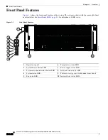
Page 4: ...le front bezel installed See Front Panel LEDs page 3 2 for definitions of LED states Figure 1 1 Front Panel Features 1 Operations panel 6 Temperature status LED 2 System Power button LED 7 Power supply status LED 3 System unit identification button LED 8 Network link activity LED 4 System status LED 9 Pull out asset tag not visible under front bezel 5 Fan status LED 10 Internal drive status LEDs 3...

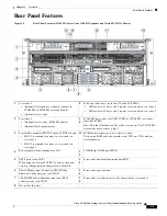
Page 5: ... This label identifies an M4 or M5 server node The C3X60 M3 server node does not have a label 3 System I O controller SIOC Version 03 SIOCs shown SIOC 1 is required if you have a server node in server bay 1 SIOC 2 is required if you have a server node in server bay 2 11 KVM console connector one each server node Used with a KVM cable that provides two USB one VGA and one serial connector 4 Power s...

Page 6: ...ts Inside the Main Chassis This section shows the locations of the replaceable components that are inside the main chassis Some components are accessible from the rear panel and others are accessible by opening the top covers The top view of the system in Figure 1 3 shows the top covers open Note The internal drives and cooling fans in the system are hot swappable and are accessed by opening the t...

Page 7: ...ules four hot swappable Each fan module contains two fans 5 System I O controllers SIOCs one or two 2 Top loading drive bays up to 56 3 5 inch HDDs or SSDs hot swappable 6 Power supplies four redundant as 3 1 3 Server bay 1 Optional I O expander as shown with M4 or M5 server node only Optional server node 7 2 5 inch SAS SSDs up to four 4 Server bay 2 Optional server node C3X60 M4 shown Optional di...

Page 8: ...isco UCS C3X60 M4 Server Node For Cisco UCS S3260 System Service Note Cisco UCS S3260 M5 Server Node For Cisco UCS S3260 System Service Note Components Inside the I O Expander The C3X60 M4 or S3260 M5 server node might include an optional I O expander that attaches to the top of the server node For the locations of the replaceable components that are inside an I O expander see the service note for...

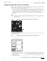
Page 9: ...ent is an RTC battery The Version 03 SIOC UCS S3260 PCISIOC uses a removable PCIe style adapter card half height half length Gen 3 x8 lane It also supports up to two 2 5 inch NVMe SSDs and an RTC battery Note The Version 03 SIOC is supported only with S3260 M5 server node It is not supported with earlier server nodes Figure 1 4 Replaceable Components Inside the Version 02 SIOC UCSC S3260 SIOC Figu...

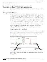
Page 10: ...nage the server nodes BMCs via the Cisco IMC interface you physically connect to the ports on a SIOC When you log into the Cisco IMC interface you use a system management IP address Each CMC and each BMC also has an IP address for internal communication All user interfaces run only on the active CMC Configuration changes are automatically synchronized between the active and standby CMCs The active...

Page 11: ...1 9 Cisco UCS S3260 Storage Server Chassis Installation and Service Guide Chapter 1 Overview Overview of Cisco UCS S3260 Architecture Figure 1 7 Management Architecture ...

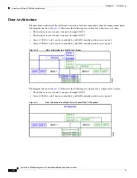
Page 12: ...ough SIOC 1 The data bus in server node 2 connects through SIOC 2 Server 1 SSDs 1 and 2 can be controlled by a RAID controller card in server node 1 Server 2 SSDs 1 and 2 can be controlled by a RAID controller card in server node 2 Figure 1 8 Data Architecture in a Dual Server System The diagram shown in Figure 1 9 illustrates the following associations for a single server system The data bus in s...

Page 13: ...5 inch hard drives Up to four 3 5 inch rear loading hard drives in an optional disk expansion tray Up to four 2 5 inch rear loading SATA solid state drives SSDs M4 server node one 2 5 inch NVMe SSD inside each server node M5 server node two 2 5 inch NVMe SSDs inside each server node Version 03 SIOC only two 2 5 inch NVMe SSDs inside each SIOC Disk Management The system supports up to two storage c...

Page 14: ... be used with a KVM cable which provides two USB one VGA DB 15 and one serial DB 9 connector Power Four power supplies hot swappable and redundant as 3 1 All installed power supplies must be identical Cooling Four internal fan modules that pull front to rear cooling hot swappable Each fan module contains two fans Baseboard management Cisco Integrated Management Controller Cisco IMC firmware Depend...

Page 15: ...irmware page 2 20 Note Before you install operate or service a system review the Regulatory Compliance and Safety Information for Cisco UCS S Series Servers for important safety information Warning IMPORTANT SAFETY INSTRUCTIONS This warning symbol means danger You are in a situation that could cause bodily injury Before you work on any equipment be aware of the hazards involved with electrical cir...

Page 16: ...onents wear an ESD strap and handle modules by the carrier edges only Note The chassis is thoroughly inspected before shipment If any damage occurred during transportation or any items are missing contact your customer service representative immediately Step 1 Remove the system from its cardboard container and save all packaging material Step 2 Compare the shipment to the equipment list provided b...

Page 17: ...rcuit overcurrent protection Ensure that the protective device is rated not greater than 250 V 15 A Statement 1005 Warning Installation of the equipment must comply with local and national electrical codes Statement 1074 When you are installing a system use the following guidelines Plan your site configuration and prepare the site before installing the system See the Cisco UCS Site Preparation Gui...

Page 18: ...e per system must be four RUs equal to 7 in 17 78 cm There must be a minimum of 48 inches clearance at the front of the rack Equipment Requirements The slide rails supplied by Cisco Systems for this system do not require tools for installation if you install them in a rack that has square 0 38 inch 9 6 mm round 0 28 inch 7 1 mm or 12 24 UNC threaded holes Slide Rail Adjustment Range The slide rail...

Page 19: ...d with stabilizing devices install the stabilizers before mounting or servicing the unit in the rack Statement 1006 Installing the Slide Rails Caution This system weighs approximately 190 pounds 86 kilograms when fully loaded with components We recommend that you use a mechanical lift when lifting the system Attempting this procedure without a lift could result in personal injury or equipment dama...

Page 20: ...l marked R to the right side of the chassis as viewed from the front Figure 2 2 Attaching Inner Rail to Sides of the Chassis Step 3 Install the slide rails into the rack see Figure 2 3 Note The slide rail assemblies are not identical there is a left rail and a right rail as viewed from the rack front The assemblies are marked with L for left or R for right a Align the front end of the left side sl...

Page 21: ... e Release the rear peg spring latch to lock the rear pegs in place Caution Ensure that all pegs are fully inserted into the rack post holes before installing the chassis to the rack f Attach the right side slide rail assembly marked R to the right side of the rack g Ensure that the two slide rail assemblies are at the same height and are level front to back Also ensure that the right side and lef...

Page 22: ... chassis sides with the front ends of the empty intermediate rails on the rack Caution Ensure that the inner rails on the chassis are parallel with the intermediate rails on the rack This could require adjusting the mechanical lift position up down and left to right Consider using shims if your lift does not support these motions The ends of the inner rail must align up down and side to side with ...

Page 23: ...rail on the rack post and prevents the chassis from being pulled out Repeat for the opposite slam latch Caution When you pull the chassis outward from the rack it stops at internal locking stops Do not depress the release clips on the inner rails see Figure 2 4 unless you intend to slide the chassis back into the rack or to fully remove the chassis from the rack Depressing the release clips on the...

Page 24: ...MA tab of the CMA arm that is farthest from the system onto the end of the stationary slide rail that is attached to the rack post see Figure 2 5 Slide the tab over the end of the rail until it clicks and locks Step 2 Slide the CMA tab that is closest to the system over the end of the inner rail that is attached to the system see Figure 2 5 Slide the tab over the end of the rail until it clicks an...

Page 25: ...ure 2 5 Attaching the Cable Management Arm to the Rear of the Slide Rails 1 CMA tab on arm farthest from system and end of stationary outer slide rail 3 CMA tab on width adjustment slider and end of stationary outer slide rail 2 CMA tab on arm closest to the system and end of inner slide rail attached to system 4 Rear of system 352584 1 4 2 3 ...

Page 26: ...ides must remain pointing upward Step 2 Flip the tabs at the end of each CMA arm so that they point toward the rear of the system Step 3 Pivot the tab that is at the end of the width adjustment slider Depress and hold the metal button on the outside of the tab and pivot the tab 180 degrees so that it points toward the rear of the system Figure 2 6 Reversing the CMA 1 CMA tab on end of width adjust...

Page 27: ...tup Utility page 2 15 5 Make networking settings using the Cisco IMC Configuration Utility Setting Up the System Using the Cisco IMC Configuration Utility page 2 16 6 Static IPs only Set CMC and BMC IP addresses using the Cisco IMC management interface Setting Static CMC and BMC Internal IP Addresses page 2 18 Default Networking Settings The system is shipped with these settings The default NIC mo...

Page 28: ...in SIOC 2 if installed This address can be assigned by your DHCP server or you can set a static address by using the Cisco IMC interface Server 1 BMC IP This is the internal address for the board management controller BMC in server node 1 This address can be assigned by your DHCP server or you can set a static address by using the Cisco IMC interface Server 2 BMC IP This is the internal address fo...

Page 29: ...e KVM connector on either server node at the rear of the system Step 3 Connect a USB keyboard and a VGA monitor to the KVM cable Step 4 Connect QSFP cables to the QSFP connectors on both SIOCs Note If you plan on changing the NIC mode to use the dedicated management port to manage the server also attach an RJ 45 Ethernet cable to the management port on the SIOCs Step 5 Press and hold the front pan...

Page 30: ...cture page 1 8 b NIC redundancy There are three possible NIC redundancy settings Active active default All QSFP ports are utilized simultaneously This setting can be used only with the Cisco Card NIC mode Active standby If an active QSFP port fails traffic fails over to a standby port This setting can be used only with the Cisco Card NIC mode None The ports operate independently and do not fail ov...

Page 31: ...files and the port name Note Save your changes by pressing F10 before switching windows Step 11 Press F1 to go to the third settings window then continue with the next step From the third window you can press F2 to switch back to the first window Step 12 Optional Set the port speed for the SIOC QSFP ports to either 40 Gbps or 4x10 Gbps Adapter 1 refers to SIOC 1 and Adapter 2 refers to SIOC 2 if p...

Page 32: ...nnect to the Cisco IMC management interface Step 2 Log in at the login page The default user name for the system is admin The default password is password The Chassis Summary page opens The Management IP Address is displayed The IP address for each CMC is displayed at this point only if a DHCP server assigned them Step 3 Click the menu button at the upper left corner and select Admin Networking Th...

Page 33: ...ou must select a NIC redundancy setting Dedicated The dedicated RJ 45 management port of either SIOC is used to access the Cisco IMC The only NIC redundancy setting for this NIC mode is None NIC Redundancy You can choose from the following NIC redundancy settings Active active default All QSFP ports are utilized simultaneously This setting can be used only with the Cisco Card NIC mode Active stand...

Page 34: ...ended method is to use the Cisco Host Upgrade Utility to simultaneously upgrade the Cisco IMC BIOS and other component firmware to compatible levels See the Cisco Host Upgrade Utility Quick Reference Guide for your firmware level Accessing the System BIOS Note Details about the BIOS settings are displayed in the BIOS windows Step 1 Enter the BIOS setup utility by pressing the F2 key when prompted ...

Page 35: ...ponents Status LEDs and Buttons page 3 1 Preparing for System Component Installation or Replacement page 3 9 Installing or Replacing System Components page 3 15 Service Headers on the Server Node Board page 3 49 Status LEDs and Buttons This section describes the location and meaning of LEDs and buttons and includes the following topics Front Panel LEDs page 3 2 Rear Panel LEDs and Buttons page 3 4...

Page 36: ...LED 7 Network link activity LED 4 Fan status LED 8 Internal drive status LEDs Table 3 1 Front Panel LEDs States LED Name State 1 System Power button power status LED Off There is no AC power to the system all power cords are disconnected Amber Both server nodes are powered off Pressing the button will power on both server nodes Green At least one server node is powered on Pressing the button will ...

Page 37: ...ure sensors have exceeded a critical threshold 6 Power supply status Green All power supplies are operating normally Amber steady One or more power supplies are in a degraded operational state An event warning threshold has been reached but the power supply continues to operate Amber blinking One or more power supplies are in a critical fault state A critical fault threshold has been reached causi...

Page 38: ...ation button LED on each server node 9 10 100 1000 dedicated management port link activity LED on each SIOC 3 1 Gb Ethernet port link speed LED on each M5 server node only 10 10 100 1000 dedicated management port link speed LED on each SIOC 4 1 Gb Ethernet port link activity LED on each M5 server node only 11 Solid state drive activity LED each drive bay 5 Power supply status LED each power supply...

Page 39: ...wer supply status on each power supply unit AC Power Supplies Off No AC power input Green steady The power supply is operating normally and supplying DC power to the system Green blinking AC power is OK DC output not enabled standby mode Amber blinking An event warning threshold has been reached but the power supply continues to operate Amber steady A critical fault threshold has been reached caus...

Page 40: ...ve activity Off There is no drive connected Green Drive connected no activity Green blinking The drive is reading or writing data 12 Solid state drive fault Off The drive is operating properly Amber This drive has failed or the Locate function has been activated for the drive 13 Not used at this time 14 SIOC health Off System is idle Green SIOC is working normally Green blinking There is a problem...

Page 41: ...r the locations of these internal LEDs See Table 3 4 for definitions of the LED states Figure 3 3 Internal Diagnostic LED Locations in the Main Chassis 1 Drive fault on each drive carrier 3 Fan module fault on each fan module 2 Drive activity on each drive carrier 353446 HDD01 HDD02 HDD03 HDD04 HDD05 HDD06 HDD07 HDD08 HDD09 HDD10 HDD11 HDD12 HDD13 HDD14 HDD15 HDD16 HDD17 HDD18 HDD19 HDD20 HDD21 HD...

Page 42: ...sco UCS C3X60 M4 Server Node For Cisco UCS S3260 System Service Note Cisco UCS S3260 M5 Server Node For Cisco UCS S3260 System Service Note Table 3 4 Internal Diagnostic LED States LED Name State 1 SAS drive fault Off The drive is operating properly Amber This drive has failed Amber blinking The device is rebuilding 2 SAS drive activity Off There is no drive in the drive tray no access no fault Gr...

Page 43: ...spare Shutting Down and Powering Off the S3260 System You can invoke a graceful shutdown or a hard shutdown of the entire S3260 system by using either the Cisco IMC interface or the system power button on the front panel Caution To completely remove power from the system you must disconnect power cords from all power supplies You can also shut down an individual server node rather than the entire ...

Page 44: ...tons for the server that you want to shut down Caution To avoid data loss or damage to your operating system you should always invoke a graceful shutdown of the operating system Do not power off a server if any firmware or BIOS updates are in progress Shut Down Performs a graceful shutdown of the operating system Power Off Powers off the chosen server even if tasks are running on that server It is...

Page 45: ...4 seconds to force the power off the server node When the server node power button turns amber it is safe to remove the server node from the chassis Removing Chassis and Component Covers This section contains the following topics Opening the Main Chassis Top Covers page 3 12 Removing a Server Node Cover page 3 13 Removing an I O Expander Cover C3X60 M4 and S3260 M5 Server Nodes Only page 3 13 Remo...

Page 46: ...er to access the hot swappable internal drives a For either the right or left side cover pull the latch release buttons on both latches toward the outer edges of the chassis This causes the spring loaded latches to pop up b With both latches open swing open the hinged cover from the center toward the outside c To secure the cover close it down flat and then push both latches flat until they click ...

Page 47: ...0 System Service Note Cisco UCS S3260 M5 Server Node For Cisco UCS S3260 System Service Note Removing the System I O Controller SIOC Cover Note You do not have to slide the system out of the rack to remove the SIOC from the rear of the system Step 1 Power off the server node that is paired with the SIOC that you are replacing SIOC 1 is paired with server node1 SIOC 2 is paired with server node 2 S...

Page 48: ...erver node that you powered off in the first step Figure 3 5 Removing the SIOC Cover Version 02 SIOC UCS S3260 SIOC Figure 3 6 Removing the SIOC Cover Version 03 SIOC UCS S3260 PCISIOC 1 SIOC cover 2 Cover screws four two on each side of the SIOC 305042 1 2 2 1 SIOC cover including ejector levers 3 Four securing screws on sides of cover two each side 2 Two securing screws on top of cover ...

Page 49: ...ves in the Rear Panel Bays page 3 23 Replacing Fan Modules page 3 25 Replacing a Server Node page 3 26 Replacing a Disk Expansion Tray page 3 27 Replacing a System I O Controller SIOC page 3 28 Replacing a Power Supply page 3 33 Replacing DIMMs Inside a Server Node page 3 36 Replacing CPUs and Heatsinks Inside a Server Node page 3 36 Replacing a Storage Controller Card Inside the Server Node page ...

Page 50: ...refore will not work with 6 TB drives Setting Up Booting in UEFI Mode in the BIOS Setup Utility Step 1 Use a web browser and the management IP address of the system to log into the Cisco IMC GUI management interface Step 2 Select Compute and then Server 1 Step 3 Click Launch KVM to open a virtual KVM window for the server node Step 4 In the Launch KVM dialog select Server 1 and click Launch Step 5...

Page 51: ...he information for the 4K sector format drive Enter a name and specify Slot M Step 10 Click Save Changes Step 11 Click Add Virtual Media Step 12 In the Add Virtual Media dialog enter a name for your OS installation virtual media Step 13 Click Save Changes Step 14 Click Close Step 15 Click Launch KVM to open a virtual KVM window for the server node Step 16 In the Launch KVM dialog select Server 1 a...

Page 52: ...d bays to the highest Populate row 1 14 then row 15 28 and so on Populate internal SSDs starting from the highest numbered bays to the lowest Populate bay 56 then bay 55 and so on For example a system with 36 HDDs and 2 SSDs should have the HDDs in bays 1 36 and the SSDs in bays 56 and 55 The four colored boxes shown in Figure 3 7 represent the four power groups in which power is distributed to th...

Page 53: ...ee Figure 3 8 for an example In this example the amber LED indicates that the failing drive is in the right half of the internal drive compartment in row 3 Step 2 Open the right or left side cover and look at the fault LEDs on the drive trays A solid amber fault LED indicates a failed drive Figure 3 8 Internal Drive Status LED Example 1 Internal drive fault LEDs on right front handle of system ind...

Page 54: ...nal drive compartment cover Step 4 Remove the faulty drive a Press the release button on the drive carrier The drive lever pops up b Lift the drive lever to the fully open 90 degree position then lift the drive straight up out of its bay Spare drives are already installed in a carrier so it is not necessary to remove the old drive from its carrier Step 5 Install a new drive Note Observe the drive ...

Page 55: ...guidelines Populate drives starting from the lowest numbered bay to the highest Figure 3 10 Disk Expansion Tray and Solid State Drive Numbering Identifying a Faulty Disk Expansion Tray Drive Each drive has a fault LED that lights solid amber to indicate a failing drive Replacing Drive Expander Module Drives Note SAS SATA drives are hot swappable and can be replaced without removing power from the ...

Page 56: ...stall a new drive a Align the new drive with the empty bay and then push the drive in until it touches the board connector and the drive lever begins to close b Press the drive lever down flat until it clicks and locks Figure 3 11 Drive Expander Module Drive Carrier Features 1 Drive lever 3 Drive fault LED 2 Release button 4 Drive activity LED 353455 4 3 1 2 ...

Page 57: ...rolled pair If a pair of SSDs is not present keep the blanking panel in the empty two SSD bays to ensure proper air flow see Figure 3 12 Identifying a Faulty Solid State Drive Each solid state drive bay has a fault LED that lights solid amber to indicate a failing drive see Rear Panel LEDs and Buttons page 3 4 Replacing Solid State Drives Note SAS SATA solid state drives are hot swappable and can ...

Page 58: ...uide Chapter 3 Maintaining the System Installing or Replacing System Components Figure 3 12 Solid State Drive Bay Features 1 SSD release latch 3 Solid state drive activity LED each bay 2 Solid state drive fault LED each bay 4 Blanking panel over lower bays when not in use ...

Page 59: ...m from the rack Step 2 Open the fan compartment cover as described in Opening the Main Chassis Top Covers page 3 12 Step 3 Remove the fan module a Grasp the two latches on the top of the fan and pinch them toward the center b Lift the fan module straight out of the bay Step 4 Install a new fan module Note The arrow on the fan module that indicates the air flow direction should point to the rear of...

Page 60: ...ither server bay Note Whichever bay a server node is installed to it must have a corresponding SIOC That is a server node in bay 1 must be paired with a SIOC in SIOC slot 1 a server node in bay 2 must be paired with a SIOC in SIOC bay 2 See Overview of Cisco UCS S3260 Architecture page 1 8 for more information To replace a server node including exporting and importing its configuration see the ser...

Page 61: ...t from the rack Step 1 Remove a disk expansion tray from the system a Grasp the two ejector levers and pinch their latches to release the levers see Figure 3 14 b Rotate both levers to the outside at the same time to evenly disengage the tray from the midplane connectors c Pull the tray straight out from the system Step 2 Remove any drives from the old tray and move them to your new disk expansion...

Page 62: ...on 02 SIOC UCSC S3260 SIOC with a Version 03 SIOC UCS S3260 PCISIOC use the procedure in Migrating From Version 02 SIOC to Version 03 SIOC page E 14 Version 03 SIOCs require Cisco IMC 4 0 1n or later and for UCS Manager controlled systems Cisco UCS Manager 4 0 1n or later Note The Version 03 SIOC is supported only with S3260 M5 or later server nodes Note Do not mix different versions of SIOCs in t...

Page 63: ...placing a PCIe Adapter Card Inside the S3260 SIOC Version 03 SIOC Only page 3 40 c Remove the NVMe SSDs as described in Replacing an NVMe SSD Inside the S3260 SIOC Version 03 SIOC Only page 3 42 d Remove the cover from the replacement Version 03 SIOC e Install the adapter card to the replacement SIOC as described in Replacing a PCIe Adapter Card Inside the S3260 SIOC Version 03 SIOC Only page 3 40...

Page 64: ...lacing a PCIe Adapter Card Inside the S3260 SIOC Version 03 SIOC Only page 3 40 c Remove the NVMe SSDs as described in Replacing an NVMe SSD Inside the S3260 SIOC Version 03 SIOC Only page 3 42 d Remove the cover from the new Version 03 SIOC e Install the adapter card to the replacement SIOC as described in Replacing a PCIe Adapter Card Inside the S3260 SIOC Version 03 SIOC Only page 3 40 f Instal...

Page 65: ...that is not associated with a server node SIOC 1 is associated with a server node in bay 1 SIOC 2 is associated with a server node in bay 2 In this case you must manually upgrade the adapter firmware on the un associated SIOC Using the Cisco IMC GUI Interface to Update SIOC Adapter Firmware page 3 31 Using the Cisco IMC PMCLI Interface to Update SIOC Adapter Firmware page 3 32 Using the Cisco IMC ...

Page 66: ...e path activate no activate SIOC slot number For example server1 chassis update adapter fw tftp nnn nnn nnn nnn fw image bin activate 1 Adapter firmware update has started Please check the status using show adapter detail You have chosen to automatically activate the new firmware image Please reset your adapter after the update finishes Step 2 Reset the adapter Note You must reset the adapter to m...

Page 67: ...EDs Replacing an AC Power Supply To replace or install an AC power supply follow these steps Note You do not have to power off the system to replace up to one power supply because they are redundant as 3 1 Step 1 Remove the power supply that you are replacing or a blank panel from an empty bay see Figure 3 16 a Remove the power cord from the power supply that you are replacing b Grasp the power su...

Page 68: ...Installation of the equipment must comply with local and national electrical codes Statement 1074 Caution Before beginning this wiring procedure turn off the DC power source from your facility s circuit breaker to avoid electric shock hazard Step 1 Turn off the DC power source from your facility s circuit breaker to avoid electric shock hazard Note The required DC input cable is Cisco part CAB 48D...

Page 69: ...u are replacing or a blank panel from an empty bay a Remove the CAB 48DC 40A 8AWG keyed cable connector from the power supply that you are replacing b Grasp the power supply handle while pinching the release lever toward the handle c Pull the power supply out of the bay Step 2 Install a new power supply a Grasp the power supply handle and insert the new power supply into the empty bay b Push the p...

Page 70: ...isco UCS C3X60 M3 Server Node For Cisco UCS S3260 System Service Note Cisco UCS C3X60 M4 Server Node For Cisco UCS S3260 System Service Note Cisco UCS S3260 M5 Server Node For Cisco UCS S3260 System Service Note Replacing an SSD Inside the Server Node C3X60 M4 or S3260 M5 Only To replace a solid state drive SSD inside a C3X60 M4 or S3260 M5 server node see the service note for your server node Cis...

Page 71: ... Service Note Replacing a PCIe Card Inside the I O Expander C3X60 M4 or S3260 M5 Server Nodes Only To replace a PCIe card inside an optional I O expander see the service note for your server node Cisco UCS C3X60 M4 Server Node For Cisco UCS S3260 System Service Note Cisco UCS S3260 M5 Server Node For Cisco UCS S3260 System Service Note Replacing a Storage Controller Card Inside the I O Expander C3...

Page 72: ...r Node page 3 10 Step 2 Remove the SIOC from the system a Loosen the single captive thumbscrew on the SIOC and then open its two hinged ejector levers to evenly disengage the SIOC from its midplane connector b Pull the SIOC from the system Step 3 Remove the SIOC cover as described in Removing the System I O Controller SIOC Cover page 3 13 Step 4 Gently pry under the battery to lift it from its soc...

Page 73: ...eplacing System Components Figure 3 18 RTC Battery Location Inside the Version 02 S3260 SIOC UCS S3260 SIOC Figure 3 19 RTC Battery Location Inside the Version 03 S3260 SIOC UCS S3260 PCISIOC 1 Battery socket on version 02 SIOC board with CR1632 battery 305039 1 1 Battery socket on Version 03 SIOC board with CR1632 battery ...

Page 74: ... page 3 13 Step 4 Remove an existing adapter card a Remove the SIOC side panel that is closest to the adapter card Turn the SIOC upside down and remove the three screws that secure the side panel from the underside of the SIOC b Turn the SIOC over c Slide the adapter card horizontally to disconnect its edge connector from the socket Step 5 Install a new adapter card a Set the card in place on the ...

Page 75: ...CS S3260 PCISIOC Cisco VIC Cards Supported in Version 03 SIOC UCSC S3260 PCISIOC At this time the following Cisco Virtual Interface Card VIC is supported in the Version 03 SIOC Cisco UCS VIC 1455 UCSC PCIE C25Q 04 1 Horizontal socket for adapter card 3 Location of three screws that secure the side panel access from the underside of the SIOC 2 Removable SIOC side panel three screws on underside ...

Page 76: ...SIOC is numbered for the server that supports it SERVER 1 NVME or SERVER 2 NVME Populate an NVMe SSD in SERVER 1 NVME only if you have a server node in upper server bay 1 Populate an NVME SSD in SERVER 2 NVME only if you have a server node in lower server bay 2 Note If your system configuration has an M5 server node in lower server bay 2 and an I O expander in upper server bay 1 you cannot populat...

Page 77: ... two hinged ejector levers to evenly disengage the SIOC from its midplane connector b Pull the SIOC from the system Step 3 Remove the SIOC cover as described in Removing the System I O Controller SIOC Cover page 3 13 Note The NVMe SSD sled UCS S3260 NVMSLD2 in the Version 03 SIOC is not interchangeable with the NVMe SSD sled UCS S3260 NVMSLD1 in the S3260 M5 server node Step 4 Remove the NVMe SSD ...

Page 78: ...er 3 Maintaining the System Installing or Replacing System Components 1 NVMe sled assembly thumbscrews 3 SERVER 2 NVME Populate this slot only when you have a server node in lower server bay 2 2 SERVER 1 NVME Populate this slot only when you have a server node in upper server bay 1 ...

Page 79: ... secure the SSD to the sled c Set the sled into the SIOC so that the connectors on the two SSDs align with the two sockets on the SIOC board d Slide the SSD connectors into the sockets as you tilt the sled down flat e Tighten the two thumbscrews on the sled assembly to secure it to the SIOC board standoffs Step 7 Reinstall the SIOC cover Step 8 Replace the SIOC to the system a Push the SIOC into i...

Page 80: ...ge Server Chassis Installation and Service Guide Chapter 3 Maintaining the System Installing or Replacing System Components c Tighten the thumbscrew on the SIOC levers Step 9 Power on the server node that you powered off earlier ...

Page 81: ... each to the same bay position in the new chassis See Replacing a System I O Controller SIOC page 3 28 for more information Step 7 Remove each rear panel boot SSD and install each to the same bay position in the new chassis See Replacing SAS SATA Solid State Drives in the Rear Panel Bays page 3 23 for more information Step 8 Remove each power supply and install each to the same bay position in the...

Page 82: ...hem statically using the procedure in Setting Static CMC and BMC Internal IP Addresses page 2 18 For more information about the IP addresses in the system up to five see System IP Addresses page 2 14 Step 18 After the system has connection to the network use the Host Upgrade Utility to update the system to your desired level and ensure that all components in the system are running compatible softw...

Page 83: ...Board The server node includes headers that you can jumper for certain service functions For information about the service headers see the service note for your server node Cisco UCS C3X60 M3 Server Node For Cisco UCS S3260 System Service Note Cisco UCS C3X60 M4 Server Node For Cisco UCS S3260 System Service Note Cisco UCS S3260 M5 Server Node For Cisco UCS S3260 System Service Note ...

Page 84: ...3 50 Cisco UCS S3260 Storage Server Chassis Installation and Service Guide Chapter 3 Maintaining the System Service Headers on the Server Node Board ...

Page 85: ...sical Specifications page A 1 System Environmental Specifications page A 2 Power Specifications page A 3 System Physical Specifications Table A 1 lists the physical specifications for the system Table A 1 Physical Specifications Description Specification Height 6 88 in 174 mm Width 17 46 in 444 mm Length including front handles Length including front handles and slide rails with CMA 33 54 in 852 m...

Page 86: ...the system Table A 2 Environmental Specifications Description Specification Temperature operating 5ºC to 35ºC 41ºF to 95ºF Temperature nonoperating 40ºC to 65ºC 40ºF to 149ºF Humidity operating 10 to 90 non condensing Humidity nonoperating 5 to 93 non condensing Altitude operating Derated 1ºC for each 305 m 0 m to 3048 m 0 ft to 10 000 ft Altitude nonoperating 0 m to 12 192 m 0 ft to 40 000 ft Aco...

Page 87: ...wer supplies in all UCS servers has 5 tolerance 1050 W AC Power Supply UCSC PSU1 1050W Table A 3 lists the specifications for each 1050 W AC power supply Cisco part number UCSC PSU1 1050W Table A 3 1050 W Power Supply Specifications Description Specification AC input voltage Nominal range 200 240 VAC Range 180 264 VAC AC input frequency Nominal range 50 to 60Hz Range 47 63 Hz Maximum AC input curr...

Page 88: ...s Description Specification DC input voltage range Nominal range 48 to 60 VDC nominal Range 40 to 72 VDC Maximum DC input current 32 A at 40 VDC Maximum input W 1234 W Maximum output power per PSU 1050 W on 12 VDC main power 36 W on 12 VDC standby power Maximum inrush current 35 A sub cycle duration Maximum hold up time 5 ms at 100 load 1050 W main and 36 W standby Power supply output voltage 12 V...

Page 89: ...les Note Only the approved power cables or jumper power cables provided with the server are supported Table B 1 lists the power cables for the server power supplies Table B 1 Supported Power Cables for the Server Description Length Feet Meters CAB 250V 10A BR Power cable 250 VAC 10 A Brazil 8 2 2 5 CAB 250V 10A CN Power cable 250 VAC 10 A PRC 8 2 2 5 CAB ACTW AC power cord 250 V 10 A C13 plug Taiw...

Page 90: ...AC Cabinet jumper power cable 250 VAC 10 A C13 C14 connectors recessed receptacle 9 8 3 0 CAB C13 CBN Cabinet jumper power cable 250 VAC 10 A C13 C14 Connectors 2 2 0 68 CAB C19 C20 3M JP Power cable C19 C20 connectors Japan PSE mark 9 8 3 0 CAB JPN 3PIN Power cable 90 125 VAC 12 A NEMA 5 15 Japan 7 9 2 4 CAB N5K6A NA N5000 power cable 250 VAC 6 A North America 8 2 2 5 CAB 250V 10A AR N5000 power ...

Page 91: ...For information about the storage controllers that are supported in your server node see the service note for your server node Cisco UCS C3X60 M3 Server Node For Cisco UCS S3260 System Service Note Cisco UCS C3X60 M4 Server Node For Cisco UCS S3260 System Service Note Cisco UCS S3260 M5 Server Node For Cisco UCS S3260 System Service Note ...

Page 92: ...C 2 Cisco UCS S3260 Storage Server Chassis Installation and Service Guide OL 27640 01 Appendix C Storage Controller Considerations ...

Page 93: ...S Manager 3 1 2 or later You can integrate a system that has either M3 or M4 server nodes but the system must be using Cisco IMC 2 0 13 or later firmware The Cisco UCS integration instructions are in the GUI and CLI integration guides found here Cisco UCS S3260 Server Integration with UCS Manager Guides Refer to the guide that is for the version of Cisco UCS Manager that you are using ...

Page 94: ...D 2 Cisco UCS S3260 Storage Server Chassis Installation and Service Guide Appendix D Installation for Cisco UCS Manager Integration ...

Page 95: ...erver nodes are also included in this appendix Differences Between Cisco UCS C3160 and S3260 Systems page E 2 Upgrading From S3260 With One M4 Server Node to S3260 With One M5 Server Node page E 3 Upgrading From S3260 With Two M4 Server Nodes to S3260 With Two M5 Server Nodes page E 7 Installing a Second Server Node or SIOC to the S3260 System With M5 Server Node page E 11 Migrating From Version 0...

Page 96: ...sed 2 No One in server node UCSC C3X60 R1GB UCSC C3X60 R4GB UCSC C3X60 HBA C3260with M3 server nodes 2 0 7 3 1 2 Standalone or UCSM mode UCSC S3260 SIOC Integrated VIC 1300 Series chip One or two M3 server nodes Intel Xeon v2 based 4 No One in each server node UCSC C3X60 R1GB UCSC C3X60 R4GB UCSC C3X60 HBA S3260 with M4 server nodes 2 0 13 3 1 2 Standalone or UCSM mode UCSC S3260 SIOC Integrated V...

Page 97: ... chassis versions supports all M5 system components New M5 server node running Cisco IMC 3 1 3x or later firmware the factory default Software Up to five IP addresses either configured in your DHCP server or manually entered for static IP addresses See System IP Addresses page 2 14 for more information The latest Host Upgrade Utility package for Cisco IMC 3 0 3e firmware This is used to update the...

Page 98: ...ure Step 1 Ensure that the entire Cisco S3260 system with M4 server node is running Cisco IMC 3 0 3e firmware before you begin the upgrade If the system is running an earlier version download and run the S3260 Host Upgrade Utility HUU for release 3 0 3e HUU Guides Step 2 Shut down and remove power from the entire system You must disconnect all power cords to completely remove power Step 3 Remove t...

Page 99: ...ser password Set a default user password before continuing The following are the requirements for Strong Password The password can have minimum 8 characters maximum 14 characters The password must not contain the user s name The password must contain characters from three of the following four categories English uppercase letters A through Z English lowercase letters a through z Base 10 digits 0 t...

Page 100: ... SIOC to log in to the Cisco IMC management software b Navigate to the following tab Chassis Inventory Dynamic Storage Zoning c Select the drives and then assign them to Server1 or Server2 Using the Cisco IMC CLI enter the following commands with your choices Server scope chassis Server chassis scope dynamic storage Server chassis dynamic storage assign drive server ID drive slotid list For exampl...

Page 101: ...assis versions supports all M5 system components New M5 server nodes running Cisco IMC 3 1 3x or later firmware the factory default Software Up to five IP addresses either configured in your DHCP server or manually entered for static IP addresses See System IP Addresses page 2 14 for more information The latest Host Upgrade Utility package for Cisco IMC 3 0 3e firmware This is used to update the e...

Page 102: ...ersion download and run the S3260 Host Upgrade Utility HUU for release 3 0 3e HUU Guides Step 2 Shut down and remove power from the entire system You must disconnect all power cords to completely remove power Step 3 Remove the existing M4 server nodes and replace them with new M5 server nodes See Replacing a Server Node page 3 26 for instructions Step 4 Reconnect power cables to the system Wait fo...

Page 103: ...ss F8 when the server reboots in the next step Note Set the BMC in the second server node to factory defaults also Step 11 When prompted press F8 to enter the Cisco IMC Configuration Utility again Step 12 Set a new Cisco IMC password when prompted Step 13 Configure the management CMC and BMC IP addresses for the system Note If you use a DHCP server and you already have QSFP cables attached to the ...

Page 104: ...Server Nodes Upgrading From S3260 With Two M4 Server Nodes to S3260 With Two M5 Server Nodes Server scope chassis Server chassis scope dynamic storage svbu huu sanity col2 1 vcmc chassis dynamic storage assign drive server2 27 Are you sure you want to assign drives 27 to server2 Enter yes to confirm yes assign drive operation successful ...

Page 105: ...with the active CMC in the existing SIOC Step 1 A second S3260 SIOC can be installed without removing system power a Push the SIOC into the empty SIOC bay until it stops against the internal backplane b Close the two ejector levers on the SIOC to fully engage the SIOC connector with the midplane connector c Tighten the thumbscrew on the SIOC ejector levers Step 2 Attach QSFP cabled to the QSFP por...

Page 106: ...tep 3 Verify that the server node is manageable from the S3260 Cisco IMC CLI or GUI If the new server is not displayed in the CLI or GUI then you must reset the server to factory defaults For example using the CLI S3260 Server scope chassis S3260 Server chassis show server Server ID Power state Serial number Product name PID UUID 1 on FCH1848793G UCS S3260 UCSC C3K M4SRB 36399C1B 6E9A 4E95 BEAC B9...

Page 107: ... a BMC IP address for the new server node For example using the CLI S3260 Server scope network S3260 Server cimc network set v4 addr bmc n v4 ip address S3260 Server cimc network set v6 addr bmc n v6 ip address For more information see Cisco UCS C Series Integrated Management Controller GUI Configuration Guide for S3260 Servers or the Cisco UCS C Series Integrated Management Controller CLI Configu...

Page 108: ...ystem has two Version 03 SIOCs they must have identical adapter cards Do not mix adapter cards between Version 03 SIOCs in a chassis Note Version 03 SIOCs require Cisco IMC 4 0 1n or later and Cisco UCS Manager 4 0 1n or later The upgrade process is described in the following procedure Procedure Summary 1 Ensure that the entire S3260 system with Version 02 SIOCs and M5 server nodes is running 3 1 ...

Page 109: ... and hold the front panel power button for four seconds to boot the system Watch the screen for the prompt to press F8 b During bootup press F8 when prompted to open the Cisco IMC Configuration Utility This utility has three windows that you can toggle between by pressing F1 or F2 Step 9 The utility prompts you to change the default user password Set a default user password before continuing The f...

Page 110: ...ic IPs DHCP disabled Set the CMC and BMC internal IP addresses by using the Cisco IMC interface as described in Setting Static CMC and BMC Internal IP Addresses page 2 18 Step 14 Use the Cisco IMC GUI or CLI to define drive zoning which maps the NVMe SSD drives in the Version 03 SIOC s to individual server nodes Note An NVMe SSD in the SIOC slot that is labeled SERVER 1 NVME is supported only by a...

Page 111: ...owing tab Chassis Inventory Dynamic Storage Zoning c Select the drives and then assign them to Server1 or Server2 Using the Cisco IMC CLI enter the following commands with your choices Server scope chassis Server chassis scope dynamic storage Server chassis dynamic storage assign drive server ID drive slotid list For example Server scope chassis Server chassis scope dynamic storage svbu huu sanity...

Page 112: ...are before you begin the upgrade Note Migration to S3260 with M4 server nodes is supported only with chassis part number versions 68 5286 06 and later The motherboard in these chassis versions supports all M4 system components New M4 server node running Cisco IMC 2 0 13 or later firmware the factory default Software Up to five IP addresses either configured in your DHCP server or manually entered ...

Page 113: ...ystem is running an earlier version download and run the S3260 Host Upgrade Utility HUU for release 2 0 7 or 2 0 9 Use the Host Upgrade Utility User Guide for release 2 0 7 or 2 0 9 for instructions on downloading and using the utility HUU Guides Step 2 Use the S3260 HUU for 2 0 13 to upgrade the entire system to Cisco IMC release 2 0 13 Note Use the 2 0 13 HUU from the S3260 downloads page not th...

Page 114: ...monitor to the KVM cable Step 10 Open the Cisco IMC Configuration Utility a Press and hold the front panel power button for four seconds to boot the system Watch the screen for the prompt to press F8 b During bootup press F8 when prompted to open the Cisco IMC Configuration Utility This utility has three windows that you can toggle between by pressing F1 or F2 Step 11 The utility prompts you to ch...

Page 115: ...terface as described in Setting Static CMC and BMC Internal IP Addresses page 2 18 Step 17 Use the Cisco IMC GUI or CLI to define hard drive zoning which maps the hard drives to individual server nodes Using the Cisco IMC GUI a Use the IP address of the CMC in either SIOC to log in to the Cisco IMC management software b Navigate to the following tab Chassis Inventory Dynamic Storage Zoning c Selec...

Page 116: ... five IP addresses either configured in your DHCP server or manually entered for static IP addresses See System IP Addresses page 2 14 for more information The latest Host Upgrade Utility package for Cisco IMC 2 0 7 or 2 0 9 firmware This is used to update the entire Cisco S3260 system with M3 nodes to the prerequisite firmware The Host Upgrade Utility package for Cisco IMC 2 0 13 or later firmwar...

Page 117: ...grade Utility HUU for release 2 0 7 or 2 0 9 Use the Host Upgrade Utility User Guide for release 2 0 7 or 2 0 9 for instructions on downloading and using the utility HUU Guides Step 2 Use the S3260 HUU for 2 0 13 to upgrade the entire system to Cisco IMC release 2 0 13 Boot HUU on server node 1 to upgrade the firmware for the SIOC 1 adapter boot HUU on server node 2 to upgrade the firmware in SIOC...

Page 118: ...tility has three windows that you can toggle between by pressing F1 or F2 Step 9 The utility prompts you to change the default user password Set a default user password before continuing Step 10 Set the CMCs in all SIOCs and the BMCs in all server nodes to the factory defaults The Factory Default check box has two options but you must perform two resets in this order a Select Chassis Controller Co...

Page 119: ...sco IMC GUI a Use the management IP address of the system to log in to the Cisco IMC management software b Navigate to the following tab Chassis Inventory Dynamic Storage Zoning c Select the drives and then assign them to Server1 or Server2 Using the Cisco IMC CLI enter the following commands with your choices Server scope chassis Server chassis scope dynamic storage Server chassis dynamic storage...

Page 120: ...are The Host Upgrade Utility package for Cisco IMC 2 0 13 or later firmware This is used to upgrade the system to Cisco S3260 with M4 server node requirements For instructions on downloading and using the utility see the instructions in the guide for your release HUU Guides Upgrade Considerations Note the following considerations After the upgrade you must manually define drive zoning to map the h...

Page 121: ...om the entire system You must disconnect all power cords to completely remove power Step 4 Remove all existing C3160 SIOCs from the system Step 5 Install one new S3260 SIOC UCSC S3260 SIOC into SIOC bay 1 the left bay as you face the rear of the server as shown in Figure E 4 Step 6 Remove the existing M3 server node and replace it with a new M4 server node in either server bay If your M4 server no...

Page 122: ...r the Cisco IMC Configuration Utility Step 14 Configure the networking properties for your desired IP addresses NIC mode and NIC redundancy a Be aware of the S3260 system requirement to set as many as five IP addresses See System IP Addresses page 2 14 for more information At this point in the procedure the system requires three addresses One management IP address One CMC address for the SIOC One ...

Page 123: ...r with the midplane connector c Tighten the thumbscrew on the SIOC ejector levers Step 2 Attach QSFP cabled to the QSFP ports on the second SIOC Note If you are using the Dedicated NIC mode connect an RJ 45 Ethernet cable to the dedicated management port Step 3 Assign a CMC IP address to the new SIOC If the S3260 system has been configured to use your DHCP server allow it to assign the CMC IP addr...

Page 124: ...played in the CLI or GUI go to the next step If the server is not displayed set it to factory defaults a Use a KVM cable to attach a monitor and keyboard to the KVM connector on the rear of the server that you just inserted b Boot the server node and when prompted press F8 to enter the Cisco IMC Configuration Utility c Press F1 to go to the second screen of the utility d Select the Factory Default...

Reviews: