3-4
Cisco UCS C420 Server Installation and Service Guide
OL-27640-01
Chapter 3 Maintaining the Server
Status LEDs and Buttons
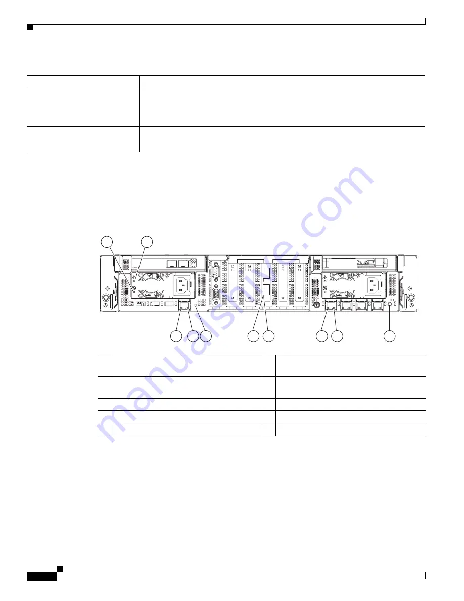
Rear-Panel LEDs and Buttons
Figure 3-2
shows the rear-panel LEDs and buttons.
Table 3-2 on page 3-5
defines the rear-panel LED
states.
Figure 3-2
Rear-Panel LEDs and Buttons
Power supply status
•
Green—All power supplies are operating normally.
•
Amber, steady—One or more power supplies are in a degraded operational state.
•
Amber, blinking—One or more power supplies are in a critical fault state.
Network link activity
•
Off—The Ethernet link is idle.
•
Green—One or more Ethernet LOM ports are link-active.
Table 3-1
Front-Panel LEDs States (continued)
LED Name
State
1
Power supply status
6
10-Gb Ethernet link status
(present only if 10-Gb VIC is installed)
2
Power supply fault
7
10-Gb Ethernet link speed
(present only if 10-Gb VIC is installed)
3
10/100/1000 Ethernet link speed
8
1-Gb Ethernet link speed
4
10/100/1000 Ethernet link status
9
1-Gb Ethernet link status
5
System status
10
Rear identification button and LED
PCle 2
PCle 5
PCle 3
PCle 6
PCle 1
PSU 1
PCle 7
PSU 2
3
4
5
8
9
1
2
10
334351
6
7


