


C-4
Cisco UCS C420 Server Installation and Service Guide
OL-27640-01
Appendix C RAID Controller Considerations
RAID Controller Cabling
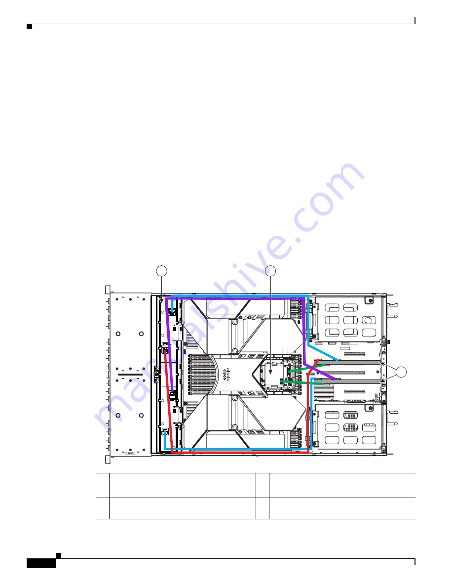
Example 2—Two Nonexpanders and Two RAID Controllers with 16 Drives
Figure C-2
shows an example of a server that is using two RAID controllers in PCIe slots 3 and 5 and
two nonexpander transition cards to control eight drives in each of the two modular drive bays.
Four RAID cables are required (2 x UCSC-CABLE-L and 2 x UCSC-CABLE-S).
•
The upper
blue
line is a 0.8m cable (UCSC-CABLE-S) from the slot 5 RAID controller SAS 0
connector to the nonexpander connector for PORT 1–4.
•
The upper
red
line is a 1m cable (UCSC-CABLE-L) from the slot 5 RAID controller SAS 1
connector to the nonexpander connector for PORT 5–8.
•
The
violet
line is a 1m cable (UCSC-CABLE-L) from the slot 3 RAID controller SAS 0 connector
to the nonexpander connector for PORT 1–4.
•
The lower
blue
line is a 0.8m cable (UCSC-CABLE-S) from the slot 3 RAID controller SAS 1
connector to the nonexpander connector for PORT 5–8.
•
The
green
lines are the cables from the two RAID controllers to their respective SCPM backup units.
Figure C-2
RAID Controller Cabling Guidelines, Two Nonexpanders and Two Controllers
1
Transition cards, nonexpander version
(shown with fan tray removed)
3
RAID controller cards in PCIe slots 3 and 5
2
SCPM backup units
(two, mounted to trays on air baffle)
1
2
3
334646