


Connect each AC power supply to a dedicated power source (branch circuit). Each AC input power supply
operates at a nominal input level of 200 to 240 VAC.
Note
Procedure
Step 1
Check that the power switch is set to the OFF (0) position. The power switch is on the right of the power tray.
Step 2
Check that the circuit breaker assigned to the AC power source you are connecting is set to off.
Step 3
Verify that the permanent ground connection (central office grounding system) has been installed to the NEBS
grounding location on the chassis.
To ensure that power remains off while you are performing this procedure, lock-out/tag-out the
circuit breaker switch in the OFF (0) position until you are ready to turn it on.
Warning
Step 4
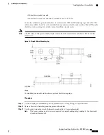
Plug the AC power cord into the receptacle at the rear of the AC power tray.
Step 5
Tighten the screw that clamps the AC power cord plug in place.
Figure 27: Typical AC Power Connections to an AC Power Tray
Step 6
Plug the other end of the AC power cord into the AC source receptacle.
Step 7
Proceed to the
Powering On the Chassis, on page 49
.
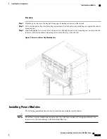
Connecting Power to a DC-Powered Chassis
This section contains the procedures to connect the DC source power cables to a DC-powered chassis.
Hardware Installation Guide for Cisco NCS 4000 Series
44
Installing Power Components
Connecting Power to the Chassis


