


Procedure
Step 1
Disconnect all cables from the ECU faceplate.
Step 2
Loosen the two captive screws.
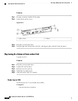
Figure 72: ECU
2 - Ejector
1 - Captive Screw
Step 3
Rotate the ejectors to point down.
Step 4
Grasp the upper and lower portions of the ECU with fingers to pull out the ECU from the chassis.
Replacing the External Connection Unit
To replace the ECU:
Procedure
Step 1
Rotate the ejectors to point down.
Step 2
Push the ECU into the chassis.
Step 3
Rotate the ejectors to point up.
Step 4
Tighten the two captive screws.
Step 5
Connect all cables to the ECU faceplate.
Replacing an SSD
The ECU houses two 2.5-in. solid-state drives (SSDs).
Prerequisites
•
Open the front door, if installed.
Hardware Installation Guide for Cisco NCS 4000 Series
136
Removing and Replacing Chassis Components
Replacing the External Connection Unit


