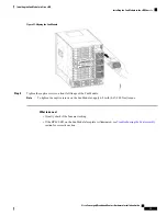
Before performing any of the following procedures, ensure that power is removed from the DC circuit.
Statement 1003
Warning
Only trained and qualified personnel should be allowed to install, replace, or service this equipment.
Statement
1030
Warning
The DC FPEM provides terminal blocks for facility input connectivity. It has 12 sets of input terminal blocks
to provide each power module with the option of both A and B facility connections.
The table below provides the common input range and circuit breaker requirements:
Table 31: Common DC Input Range and Circuit Breaker Requirements
AWG # Wire
Circuit Breaker (in A)
System Input
Rating (in A)
DC Power
Maximum
Minimum
Maximum
Minimum
AWG # 2
AWG # 4 or
AWG # 6
Always 60
2 feeds of 60 A
per DC Power
Module
DC FPEM
2
If AWG #2 wire is used for DC power module connections, the chassis ground wire must also be
upgraded to an AWG #2 wire and connector .
Before you begin
•
Attach the Chassis Ground Connection
.
•
Install the DC Power Cassette Module
.
•
.
•
• The color coding of the DC-input power supply leads depends on the color coding of the DC power
source at your site. Typically, green or green/yellow is used for ground (GND), black is used for -48V
on negative (-) terminal and red is used for RTN on the positive (+) terminal. Ensure that the lead color
coding you choose for the DC-input power supply matches lead color coding used at the DC power
source.
• For DC input power cables, select the appropriate wire gauge based on the National Electrical Code
(NEC) and local codes for 60-amp service at nominal DC input voltage (-48 VDC). Two pairs of cable
leads, source DC (-) and source DC return (+) on P-A and P-B, can be used for each DC Power Module.
These cables are available from any commercial cable vendor. All input power cables for the chassis
must have the same wire gauge.
Cisco Converged Broadband Routers Hardware Installation Guide
86
Installing the Power System in the Cisco cBR Chassis
Connecting Power to the DC-Powered Cisco cBR Chassis


