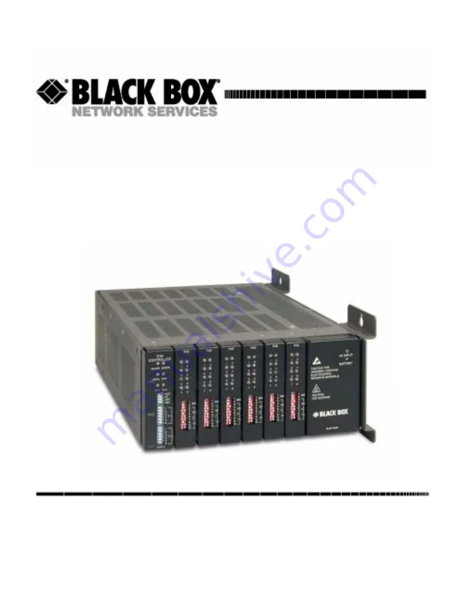
background image

Compact T1

QUICK START GUIDE

CUSTOMER

SUPPORT

INFORMATION

Order toll-free in the U.S.: Call 877-877-BBOX (outside the U.S. call 724-746-5500)
FREE  technical support, 24 hours a day, 7 days a week: Call 724-746-5500 or fax 724-746-0746 
Mail order: Black Box Corporation, 1000 Park Drive, Lawrence, PA 15055-1018 
Web site: www.blackbox.com  •  E-mail: [email protected]

M

AY

 2003

P

RODUCT

 P/N MT850A

002-0162-0001

Summary of Contents for MT850A

Page 1: ...77 BBOX outside the U S call 724 746 5500 FREE technical support 24 hours a day 7 days a week Call 724 746 5500 or fax 724 746 0746 Mail order Black Box Corporation 1000 Park Drive Lawrence PA 15055 1018 Web site www blackbox com E mail info blackbox com MAY 2003 PRODUCT P N MT850A 002 0162 0001 ...

Page 2: ...Supporting Software Version Controller 6 1 IP Router 1 6 CMG Router 2 0 ...

Page 3: ...as high as 300 VAC may be present across the transmit and receive pairs l Only use No 26 AWG or larger telecommunication line cord to reduce the risk of fire l Never install telephone wiring during a lightning storm l Never install telephone jacks in wet locations unless the jack is specifically designed for wet locations l Refer to the installation section of this manual for a safe and proper ins...

Page 4: ... wrist grounding strap and attach it to a metal part of the system unit before handling components If a wrist strap is not available maintain contact with the system unit throughout any procedure requiring ESD protection WARNING INTEGRATED CIRCUITS ICS ARE EXTREMELY SUSCEPTIBLE TO ELECTROSTATIC DISCHARGE UNLESS YOU ARE A QUALIFIED SERVICE TECHNICIAN WHO USES TOOLS AND TECHNIQUES THAT CONFORM TO AC...

Page 5: ...tion Environment n Assembly of Compact T1 n Wall Mounting n Rack Mounting Optional Feature n Compliant Installation n Chassis Connectors and Buttons n Interface Connectors n Local and Remote Management Option n Configuration n Controller Cards n Power Supplies n Service Cards ...

Page 6: ...ginal packing materials if possible 6 If equipment is to be installed later replace equipment in original shipping container and store in a safe place until ready to install Installation Environment The environment in which you are installing the Compact T1 must meet the following conditions l Operating temperature range 32 to 104 F 0 to 40 C l Storage temperature range 40 to 158 F 40 to 70 C l Co...

Page 7: ... the chassis l Power Supply in the POWER Slot l T1 Controller in Slot A l Service Cards can be in any slot 1 through 6 Note When an Unit is mounted to the wall cards that use the front cable connections should be loaded from Slot 6 to 1 This will minimize card access issues due to cable interference l Always install blank faceplates in any unused slots Service Card Slots 1 2 3 4 5 6 A POWER ...

Page 8: ...t on page 1 2 The Unit is delivered with a mounting bracket attached for quick and easy wall mounting as shown in the illustration above To install the unit to the wall attach the unit using the four screws provided one at each bracket foot NOTE Do not mount the Unit in any other orientation as show above Leave at least 3 5 above and below the Unit for adequate ventilation Mounting Bracket Leave a...

Page 9: ...re Rack Mounting Optional Feature Rack mounting kits are available for both 19 and 23 inch racks To rack mount the Unit follow the instructions below 1 Attach bracket ears to rack mounting bracket using four 8 32 x 3 16 screws on each side Bracket Ear Left Side View ...

Page 10: ... Mounting Optional Feature 2 Attach heat baffle to bracket ears using two 8 32 x 5 16 screws on each side 3 Attach rack mounting bracket ears to rack using two 12 24 x 5 8 rack mounting screws on each side Heat Baffle Left Side View Front View ...

Page 11: ...se 6 1 7 Quick Start Rack Mounting Optional Feature 4 Remove wall mount and screws from Unit 5 Slide the Unit into rack mounting bracket 6 Swing the front latch up to secure the Unit s and tighten thumbscrew Thumbscrew ...

Page 12: ...llowing illustration 2 Adits are mounted side by side and 10 high Compact T1 Chassis 2 RUs 3 5 in Spacing 1 RU above and below for each unit NOTE the mounting brackets are 7 inches high and will not allow units to be mounted closer than recommended Compact T1 Chassis occupies 2 RUs 1 RU free space 1 RU free space 1 RU free space 1 RU free space ...

Page 13: ... cable with a plastic tie not included Keep these cables separate from the signal cables 5 Terminate each signal cable to its appropriate connector 6 Secure the signal cables using the small holes along the bottom of the rack and plastic ties not included NOTE It is important that the Signal Cables are secured separately from the Power Cables for proper equipment operation Power Cord 48 VDC Batter...

Page 14: ...nit please contact Customer Support Ferrite Provided Intended For 1 large 1 Power AC or DC cable 3 small 2 One on each T1 cable 1 Ethernet 10Base T cable Card Ferrites Shipped with Card Intended For ISDN BRI 2 large 1 25 pair Telco cable ISDN BRI card in slot 1 3 top telco 4 6 bottom 1 Alarm cable requires a loop through the bead see drawing above OCU DP 1 large Alarm cable requires a loop through...

Page 15: ...ped with standard RJ 48C 8 pin connector jack l RS 232 craft port connector l Tip and Ring Analog Interfaces equipped with standard 25 pair Telco Connectors l 10Base T Ethernet port to be connected to a remote management tool such as Telnet or an SNMP based Network Management System with an RJ 45 8 pin connector jack l External Alarm Connector l Ground Lugs Ground Terminals Alarms AC Power Connect...

Page 16: ...g ground to lug on Unit 2 Strip insulation off wire end if necessary 3 Loosen compression screw until opening is large enough to accept ground wire 4 Insert ground wire into lug barrel beneath compression plate and tighten compression screw 5 Attach ground lug to chassis Ground Terminals Ground Lug Compression Screw Lug Barrel ...

Page 17: ...sert power cord male end to AC power source 2 Plug connector into the Unit 3 A green light should appear on the DC Input LED on the front of the Power Supply 48V Battery The 48 VDC input connector on the Unit is used for either direct DC powering of the Unit or for a Battery Backup connection when AC is used There is no power cable provided for this connector however the connector is provided The ...

Page 18: ...res into the appropriate square holes one at a time 4 Tighten screws to clamp wires 5 Ensure that no bare wire shows after the wires are installed 6 Plug connector in the 48 VDC connector as seen in the graphic and secure with set screws 7 Apply power to connector from 48 VDC power source 8 Verify with voltmeter that voltage is correct and polarity is correct 9 Plug connector in the 48 VDC connect...

Page 19: ...imum voltage across the contacts is 350 V and the maximum current is 150 mA This alarm is closed when power is off 2 Major Alarm 3 Minor Alarm The minor alarm output is available for power supply or minor alarm failure alerting The maximum voltage across the contacts is 350 V and the maximum current is 150 mA This alarm remains open when power is off 4 Minor Alarm 5 Alarm In The alarm inputs provi...

Page 20: ...it end is required The pinouts are as follows Pair Pin Location Function Color Code 1 26 1 Tip Channel 1 Ring Channel 1 White Blue Blue White 2 27 2 Tip Channel 2 Ring Channel 2 White Orange Orange White 3 28 3 Tip Channel 3 Ring Channel 3 White Green Green White 4 29 4 Tip Channel 4 Ring Channel 4 White Brown Brown White 5 30 5 Tip Channel 5 Ring Channel 5 White Slate Slate White 6 31 6 Tip Chann...

Page 21: ...Tip Channel 16 Ring Channel 16 Yellow Blue Blue Yellow 17 42 17 Tip Channel 17 Ring Channel 17 Yellow Orange Orange Yellow 18 43 18 Tip Channel 18 Ring Channel 18 Yellow Green Green Yellow 19 44 19 Tip Channel 19 Ring Channel 19 Yellow Brown Brown Yellow 20 45 20 Tip Channel 20 Ring Channel 20 Yellow Slate Slate Yellow 21 46 21 Tip Channel 21 Ring Channel 21 Violet Blue Blue Violet 22 47 22 Tip Ch...

Page 22: ...gement and performance monitoring using the Command Line Interface CLI The RS 232 craft port connects via a female DB 9 connector on the Unit The pinouts are as follows Pin Number Direction Description 1 Outbound Carrier Detect 2 Outbound Receive Data 3 Inbound Transmit Data 4 Inbound Data Terminal Ready 5 N A Signal Ground 6 Outbound Data Set Ready 7 Inbound Request to Send 8 Outbound Clear to Se...

Page 23: ...System Note a LINK LED on the back of the unit displays green when the system has a good ethernet link The pinouts are as follows Ethernet RJ 45 Pin Name Description 1 Receive Ring Receive from DS1 network 2 Receive Tip Receive from DS1 network 3 N C Not connected 4 Transmit Ring To DS1 network 5 Transmit Tip To DS1 network 6 8 N C Not connected Pin Name Description 1 Receive Receive from network ...

Page 24: ... an in band DS0 Command Line Interface CLI You can access the CLI using either of the following methods l RS 232 connected to the DB 9 port l Telnet via Ethernet 10Base T Setting up a CLI connection To connect to the CLI via the RS 232 port set up a connection to a PC serial port or dumb terminal using Hyperterm ProComm or similar terminal emulation software l Set the port settings to 9600 baud 8 ...

Page 25: ...User Manual l Initial Setup l Set Up Security l Set Up a DS1 T1 l Set Up a DS0 Channel l Set Up an Analog Port l Set Up the Router IP or CMG Cards l Establish a Static Channel Connection l Set Up a ISDN BRI Service l Set Up the OCU DP Card l Set Up a V 35 Port l Change the IP Address of the DS0 Management Channel l Upgrade the Controller Software l Upgrade the Router IP or CMG Software l Install C...

Page 26: ...yyyy Set the date used for event logging set time hh mm ss Set the time used for event logging set id id name Set a system ID name set clock1 slot port internal Set the primary clock source set clock2 slot port internal Set the secondary clock source set ethernet ip address ip addr mask Set the ethernet IP address in the conventional IP address format set ip gateway ip addr Set the IP gateway in t...

Page 27: ...Set the identification string set slot port lbo 1 9 Set the line buildout value for the DS1 set slot port linecode ami b8zs Set the linecode for the DS1 set slot port framing d4 esf tr8afdl tr8anofdl tr8b Set the framing option for the DS1 set slot port loopdetect on off Set the detection reaction to CSU loopcodes Command Description set slot port channel up Activate the channel set slot port chan...

Page 28: ...t See set ds1 command for details set slot port signal dpt gs gsrb gsw gswrb ls lscpd lsrb Set the signaling option for the port See the set fxs or set fxo command for details set slot port rxgain n Set the receive gain loss in dB See the set fxs or set fxo command for details set slot port txgain n Set the transmit gain loss in dB See the set fxs or set fxo command for details ...

Page 29: ...c IP Address Routing l Back to Back with PPP Command Description set ds0 addr type data Confirm DS0 is set to type data ds0 addr slot port channel of DS0 Example set a 1 1 24 type data connect slot port trunk slot port channel Cross connect T1 to router card Example connect a 1 1 24 6 1 1 router in slot 6 set router addr proxy Disable enable router proxy router addr slot port of router card Exampl...

Page 30: ...t the channel signaling option See set ds0 command for details connect slot port slot port Connect the channels See the connect card trunk card trunk command for details Command Description set slot port up Put the ISDN line In Service set slot mode lt3ds0 lt4to1tdm nt3ds0 Set the ISDN mode set slot port crv 1 768 Set the Call Reference Value Note value must be the same as the Access Navigator set...

Page 31: ...of the OCU DP card to apply settings to set ocudp addr up Set the OCU DP port 1 up show ocudp_card addr Show the OCU DP card settings Where ocudp_card addr slot of the OCU DP card disconnect a Disconnects all connections to slot a controller set ds0 addr type data Sets a DS0 data signaling type connect ds0 addr ocudp addr Connects DS0 in previous step to OCU DP port in previous step show connect o...

Page 32: ...cd high low rts Set the Clear to Send operation mode set slot port data invert normal Set the data mode set slot port clock source external Set the clock mode set slot port speed 56K 64K Set the speed set slot port txclkinv invert normal Set the transmit clock inversion mode set slot port rxclkinv invert normal Set the receive clock inversion mode Command Description set ipds0 down Set the DS0 man...

Page 33: ... status equipment Determine the system software level The Slot A line SW Vers will display the current software level load tftp ip addr file name or load xmodem Load the new controller system software See the load tftp and load xmodem command for more information Note must have TFTP running in the background Command Description status equipment Determine the Router software level The Router Slot l...

Page 34: ...peration Default 1 Reset configuration to factory defaults reset CLI password T1 1 T2 1 Line Coding 0 B8ZS Default 1 AMI T1 2 T2 2 Line Loopback 0 Loopback off Default 1 Loopback on T1 3 4 T2 3 4 Framing 0 ESF Extended Superframe Default 1 D4 T1 5 6 T2 5 6 Signaling Switch 3 Switch 4 Switch 5 Switch 6 Setting 0 1 1 1 TR 08 A Shelf with FDL 16 bit Alarm frame 1 0 0 0 TR 08 A Shelf with FDL 13 bit A...

Page 35: ...llow Minor alarms present LOCAL Off Remote mode DIP switches disabled Green Local mode DIP switches enabled ACO Off Normal mode No alarms are being suppressed Yellow Alarm cutoff active One or more active alarms suppressed T1 1 and T1 2 Off Off line Green Normal Red Loss of Signal LOS detected Yellow Bipolar Violation BPV detected Flashing Green Loopback active Flashing Red Loss of Frame LOF or Al...

Page 36: ... supply card has two LEDs as described in the table below LED State Description AC Input Off AC input missing or failure Green AC input present Battery Off Battery input not used Green Battery charging or operating from DC source only Yellow Battery discharging Red Battery low less than 42V ringer disabled ...

Page 37: ...ese settings allow for receive gain and losses of 9 7 6 5 4 3 2 0 2 3 4 5 6 and 7 9 1110 is not available 0 0 0 0 0 dB 0 0 0 1 9 dB 0 0 1 0 2 dB 0 1 0 0 3 dB 1 0 0 0 4 dB 7 10 Transmit Gain Loss 7 8 9 10 These settings allow for transmit gain and losses of 9 7 6 5 4 3 2 0 2 3 4 5 6 and 7 9 1110 is not available 0 0 0 0 0 dB 0 0 0 1 9 dB 0 0 1 0 2 dB 0 1 0 0 3 dB 1 0 0 0 4 dB State Loop Start Meani...

Page 38: ... These settings allow for receive gain and losses of 9 7 6 5 4 3 2 0 2 3 4 5 6 and 7 9 1110 is not available 0 0 0 0 0 dB 0 0 0 1 9 dB 0 0 1 0 2 dB 0 1 0 0 3 dB 1 0 0 0 4 dB 7 10 Transmit Gain Loss 7 8 9 10 These settings allow for transmit gain and losses of 9 7 6 5 4 3 2 0 2 3 4 5 6 and 7 9 1110 is not available Maximum setting on the 5G is 6 dB 0 0 0 0 0 dB 0 0 0 1 9 dB 0 0 1 0 2 dB 0 1 0 0 3 d...

Page 39: ...terface is active and transparently passing customer data State Description Yellow Flickering ALL Boot Software in control Green walking down Red walking up ALL Application Software in control repeated 3 5 times Red slow flash ALL In Boot Application flash code checksums did not match and Boot is waiting for application download Red ALL In Application code waiting for Controller to issue SW HW rev...

Page 40: ...Green Normal Red Loss of Signal LOS Yellow Bipolar Violation BPV Flashing Green Loopback active Flashing Yellow Yellow Alarm Remote Alarm Indication Flashing Red Slow Loss of Frame LOF or Alarm Indication Signal AIS Flashing Red Fast Self test Failure State Description Off No T1 Assignment Green Normal CD RTS Active Red CD inactive T1 side failure Yellow RTS inactive equipment side failure Flashin...

Page 41: ...Card is saving data to flash RAM do not power down VOIP Off No active VoIP calls or if the MGCP protocol is optioned down Green Active VoIP calls Red Call agent unreachable Yellow Insufficient VoIP resources to complete call LNK Off No ethernet link Green Good ethernet link 10 100 Off 10 Mb ethernet Green 100 Mb ethernet TX Off No ethernet transmit activity Green Ethernet transmit activity Yellow ...

Page 42: ...aving data to flash RAM do not power down 10 100 Off 10 Mb ethernet Green 100 Mb ethernet LNK Off No ethernet link Green Good ethernet link COL Off No current ethernet transmit collisions Yellow Ethernet collisions have occurred and have not dropped to minimum level Yellow Flashing Ethernet collision occurring TX Off No ethernet transmit activity Green Ethernet transmit activity RX Off No current ...

Reviews: