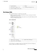


CO alarm interface (DB15)
2
Connector cover plate
1
Audible alarm
4
Alarm Cutoff (ACO) switch
3
Alarm Connector Pinout
The CO alarm connector pinout is provided in the table below.
Use a Phillips #1 screwdriver to remove the two screws that secure the cover plate over the alarm connector.
Table 14: DB15S CO Alarm Connector Pinout
Signal
Alarm Level
Pin
Normally Open
Minor
1
Normally Closed
2
Not connected
—
3
Normally Open
Major
4
Normally Closed
5
Not connected
—
6
Normally Open
Critical
7
Normally Closed
8
Minor, Common
Minor
9
Not connected
—
10
Not connected
—
11
Major, Common
Major
12
Not connected
—
13
Not connected
—
14
Critical, Common
Critical
15
Electrical Characteristics
Each of the three dry-contact, Form C relay switches is rated to support a maximum switching current of
1A@30VDC.
ASR 5500 Installation Guide
75
SSC Alarm Cabling
Alarm Connector Pinout
Summary of Contents for ASR 5500
Page 12: ...ASR 5500 Installation Guide xii Contents ...
Page 16: ...ASR 5500 Installation Guide xvi About this Guide Contacting Customer Support ...
Page 40: ...ASR 5500 Installation Guide 24 Technical Specifications Chassis Grounding ...
Page 74: ...ASR 5500 Installation Guide 58 Card Installation Save Shipping Cartons ...
Page 88: ...ASR 5500 Installation Guide 72 MIO Port Cabling Cleaning Fiber Optic Connectors ...
Page 112: ...ASR 5500 Installation Guide 96 System Power up show leds Command ...
Page 130: ...ASR 5500 Installation Guide 114 Initial System Configuration Additional Configuration Tasks ...
Page 164: ...ASR 5500 Installation Guide 148 Replaceable Components Returning Failed Components ...
Page 186: ...ASR 5500 Installation Guide 170 Console Port to Cisco Server Cabling Configuration ...
Page 192: ...ASR 5500 Installation Guide 176 RMA Shipping Procedures Rear Cards ...


