


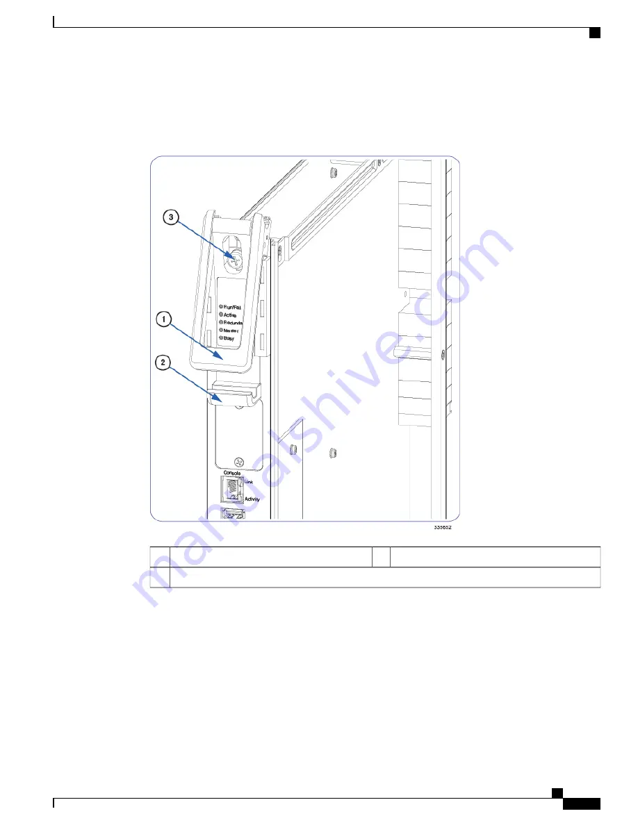
the top ejector handle against the front of the card. Tightening the captive Phillips #2 screw within the top
ejector handle secures the subhandle and circuit card to the card cage.
Figure 11: Card Ejector Handle
Ejector subhandle (interlock)
2
Ejector handle
1
Captive screw (Phillips #2)
3
Circuit Cards
The installation procedure described below is identical for all circuit cards in the chassis. Circuit cards include:
SSC, FSC, DPC/UDPC, DPC2/UDP2, MIO/UMIO.
ASR 5500 Installation Guide
53
Card Installation
Circuit Cards
Summary of Contents for ASR 5500
Page 12: ...ASR 5500 Installation Guide xii Contents ...
Page 16: ...ASR 5500 Installation Guide xvi About this Guide Contacting Customer Support ...
Page 40: ...ASR 5500 Installation Guide 24 Technical Specifications Chassis Grounding ...
Page 74: ...ASR 5500 Installation Guide 58 Card Installation Save Shipping Cartons ...
Page 88: ...ASR 5500 Installation Guide 72 MIO Port Cabling Cleaning Fiber Optic Connectors ...
Page 112: ...ASR 5500 Installation Guide 96 System Power up show leds Command ...
Page 130: ...ASR 5500 Installation Guide 114 Initial System Configuration Additional Configuration Tasks ...
Page 164: ...ASR 5500 Installation Guide 148 Replaceable Components Returning Failed Components ...
Page 186: ...ASR 5500 Installation Guide 170 Console Port to Cisco Server Cabling Configuration ...
Page 192: ...ASR 5500 Installation Guide 176 RMA Shipping Procedures Rear Cards ...