CIGWELD TRANSTIG 300 AC/DC Service Manual Download Page 119

APPENDIX 1 PARTS LIST


1

Equipment Identification

All identification numbers as described in the
Introduction chapter must be furnished when
ordering parts or making inquiries. This infor-
mation is usually found on the nameplate
attached to the equipment. Be sure to include
any dash numbers following the Part
or Assembly numbers.

2

How To Use This Parts List

The Parts List is a combination of an illustra-
tion and a corresponding list of parts which
contains a breakdown of the equipment into
assemblies, subassemblies, and detail parts.
All parts of the equipment are listed except for
commercially available hardware, bulk items
such as wire, cable, sleeving, tubing, etc., and
permanently attached items which are sol-
dered, riveted, or welded to other parts. The
part descriptions may be indented to show part
relationships. To determine the part number,
description, quantity, or application of an item,
simply locate the item in question from the
illustration and refer to that item number in the
corresponding Parts List.
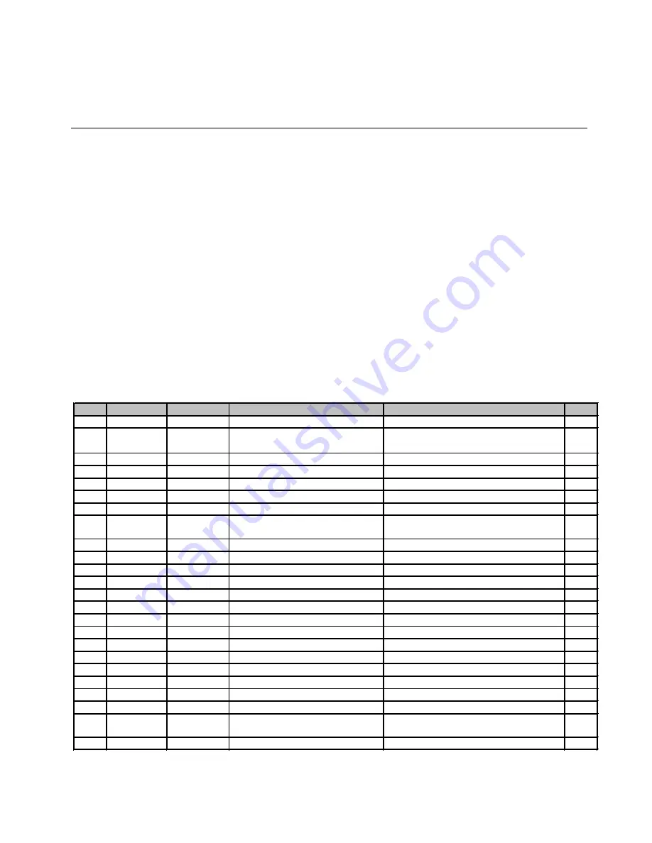
PART NUMBER:

TRANSTIG

300AC

/

DC


700723

No.

DWG No.

Part No.

Description

Additional Information

QTY.

1

CC1

W7001382

Coupling Coil, gen 3.1, IPS

F3A073800 300A AC CC

1

2

CON1

W7001666     Socket, Remote, gen 3.1, IPS            

MS3102A20-27S (NIC) 14P with 

Wiring Assembly (Remote Socket)

1

3

CT1

W7001304

Transformer, gen 3.1, IPS

F2A503001 CT 1:40

2

4

D1

10-6628

Diode, gen 3.1, IPS

DFA50BA160 (Primary Diode)

1

5

D2-7

10-6629

Diode, gen 3.1, IPS

DBA200UA60 (Secondary Diode)

6

6

FAN1

W7001307

Fan, gen 3.1, IPS

109E5724H507 DC 24V 16.8W

1

7

FCH1

W7001681

Inductor, gen 3.1, IPS

F3A040701 300A AC FCH

1

8

HCT1

10-5003

Sensor, Current, gen 3.1, IPS

HC-TN200V4B15M 200A 4V (Hall

Current Sensor)

1

9

HF.UNIT1

W7001399

HF, Unit, gen 3.1, IPS

HF.UNIT (WK-4840 U04)

1

10

10-6633

HF, Gap, gen 3.1, IPS

U0A601100

1

11

L1

W7001309

Reactor, gen 3.1, IPS

GP-7 (Ring Core)

1

12

L101

W7001400

Reactor, gen 3.1, IPS

ZCAT-3035-1330 (Ring Core)

1

13

L102

W7001672

Reactor, gen 3.1, IPS

F2A734000

1

14

L103

W7001605

Reactor, gen 3.1, IPS

SNG-25B-600

1

15

L105

W7001400

Reactor, gen 3.1, IPS

ZCAT-3035-1330

1

16

PCB1

W7001312

PCB, gen 3.1, IPS

WK-5493 U01 MAIN PCB

1

17

PCB2

W7001678

PCB, gen 3.1, IPS

WK-5597 U02 LINK PCB

1

18

PCB3

W7001314

PCB, gen 3.1, IPS

WK-5548 U01 DDC PCB

1

19

PCB4

10-6635

PCB, gen 3.1, IPS

WK-4819 U01 DETECT PCB

1

20

PCB5

W7001417

PCB, gen 3.1, IPS

WK-5551 U01 CON

N

ECT PC

B                   1

21

PCB6

W7001739

PCB, gen 3.1, IPS

WK-5549 U01-1 DC CTRL PCB

1

22

PCB7

W7001423

PCB, gen 3.1, IPS

WK-5550 U01 FILTER PCB

1

23

PCB8-11

W7001318

PCB, gen 3.1, IPS

WK-5479 U01 GATE PCB (with

IRGP20B60PD)

4

24

PCB12

W7001319

PCB, gen 3.1, IPS

WK-5527 U05 PANEL PCB

1

TRANSTIG 300 AC/DC

SERVICE MANUAL

June 30, 2008

A-1

Summary of Contents for TRANSTIG 300 AC/DC

Page 1: ...415 V 3 50 60 Hz INVERTER Service Manual TRANSTIG Revision AA Issue Date June 30 2008 Manual No 0 5002 Operating Features INVERTER ARC WELDER 300 AC DC...

Page 2: ...tions They will help you to avoid potential hazards that may exist when working with this product YOU ARE IN GOOD COMPANY The Brand of Choice for Contractors and Fabricators Worldwide CIGWELD is a Glo...

Page 3: ...3784 603 298 5711 www thermadyne com Copyright 2008 by Thermadyne Industries Inc All rights reserved Reproduction of this work in whole or in part without written permission of the publisher is prohib...

Page 4: ...03 Electrical Input Connections 3 1 3 04 Mains Supply Voltage Requirements 3 2 3 05 High Frequency Introduction 3 3 3 06 High Frequency Interference 3 3 3 07 Duty Cycle 3 4 SECTION 4 OPERATOR CONTROLS...

Page 5: ...BASIC TROUBLESHOOTING 10 1 10 01 TIG Welding Problems 10 1 10 02 Stick Welding Problems 10 4 10 03 Power Source Problems 10 7 SECTION 11 VOLTAGE REDUCTION DEVICE VRD 11 1 11 01 VRD Specification 11 1...

Page 6: ...OL1 Drive Circuitry 13 12 13 5 5 Verification of the primary Diode D1 13 12 13 5 6 Verification of the secondary Diode D2 D7 13 13 13 5 7 Verification of the primary IGBT Q1 Q24 13 14 13 5 8 Verificat...

Page 7: ...rrent Sensor HCT1 14 29 14 3 31 Primary Diode D1 14 30 14 3 32 Secondary Diode D2 D7 14 31 14 3 33 Secondary IGBT Q25 Q26 and PCB18 PCB19 14 32 14 3 34 Current Trans CT2 CT3 14 33 14 3 35 Ring Core L1...

Page 8: ......

Page 9: ...lectrical earth ground 11 Do not touch electrode while in contact with the work ground circuit 12 Use only well maintained equipment Repair or replace damaged parts at once 13 In confined spaces or da...

Page 10: ...hielding gases used for welding can displace air causing injury or death Be sure the breathing air is safe 6 Do not weld in locations near degreasing cleaning or spraying operations The heat and rays...

Page 11: ...Remove stick electrode from holder or cut off welding wire at contact tip when not in use WARNING FLYING SPARKS AND HOT METAL can cause injury Chipping and grinding cause flying metal As welds cool th...

Page 12: ...uch as fans rotors and belts can cut fingers and hands and catch loose clothing 1 Keep all doors panels covers and guards closed and securely in place 2 Stop engine before installing or connecting uni...

Page 13: ...risks To reduce magnetic fields in the workplace use the following procedures 1 Keep cables close together by twisting or taping them 2 Arrange cables to one side and away from the operator 3 Do not c...

Page 14: ...ve National Standard and Technical Specifications The product is designed and manufactured to a number of standards and technical requirements among them are AS NZS 3652 EMC Directive EN50199 applicab...

Page 15: ...t number model and serial number usually appear on a nameplate attached to the control panel In some cases the nameplate may be attached to the rear panel Equipment which does not have a control panel...

Page 16: ...AW Increase Decrease Circuit Breaker AC Auxiliary Power Remote Duty Cycle Percentage Amperage Voltage Hertz cycles sec Frequency Negative Positive Direct Current DC Protective Earth Ground Line Line C...

Page 17: ...Tungsten Arc Welding GTAW Gas Tungsten Arc Welding Pulsed GTAW P Gas Tungsten Arc Welding Sloped GTAW S and Shielded Metal Arc Welding SMAW processes The power source is totally enclosed in an impact...

Page 18: ...High Coil Frequency Unit Fan Control Circuit Gas Control Circuit Fan Solenoid Hall Current Transformer HCT1 Output Inductor Thermal Detector Input Power Secondary DC Power Voltage Sensor To each cont...

Page 19: ...150A 100 26 0V Welding Output 40 C 10 min Quoted figures refer to GTAW output 300A 25 22 0V 190A 60 17 6V 150A 100 16 0V Protection Class IP23S Cigweld continuously strives to produce the best produc...

Page 20: ...TRANSTIG 300 AC DC SERVICE MANUAL 2 6 June 30 2008 THIS PAGE LEFT INTENTIONALLY BLANK...

Page 21: ...ctive parts b In locations which are fully or partially limited by conductive elements and in which there is a high risk of unavoidable or accidental contact by the operator or c In wet or damp hot lo...

Page 22: ...e must be Correctly installed if necessary by a qualified electrician Correctly earthed electrically in accordance with local regulations Connected to the correct size 415V Mains Current Circuit as pe...

Page 23: ...diation from the machine can occur if the case is metal and is not properly grounded It can occur through apertures such as open access panels The shielding of the high frequency unit in the Power Sou...

Page 24: ...cycle ratings will cause the thermal overload protection circuit to become energized and shut down the output until the unit has cooled to normal operating temperature CAUTION Continually exceeding th...

Page 25: ...g and rotate threaded collar fully clockwise A J B K I C L N H D M G F E A B C E Front view of 14 Socket Receptacle 5k ohms Art A 07653_AB D E F H I J K L M N G Figure 4 2 14 Socket Receptacle Socket...

Page 26: ...ose welding terminal connections can cause overheating and result in the male plug being fused in the bayonet terminal 5 Gas Outlet Torch Gas Terminal is an all in one design of the Gas Outlet and the...

Page 27: ...h crater fill using a remote contactor device to control sequence REPEAT No Yes Yes 4T operation in TIG Modes with repeat operation and crater fill using a remote contactor device SPOT No Yes No 2T op...

Page 28: ...UR This parameter operates in SLOPE or REPEAT 4T TIG modes only and is used to set the start current for TIG The Start Current remains on until the torch trigger switch is released after it has been d...

Page 29: ...4T TIG modes only and is used to set the finish current for TIG The CRATER Current remains ON until the torch trigger switch is released after it has been depressed The SAVE LOAD buttons are used to...

Page 30: ...80A 1A Yes No No SPOT TIME 0 5 to 5 0 sec 2 sec 0 1 sec No Yes Yes PULSE WIDTH 15 to 80 50 1 No Yes Yes PULSE FREQ 0 5 to 500Hz 100 0Hz See Table 4 5 No Yes Yes AC FREQUENCY 15 to 150Hz 60Hz 1Hz Yes...

Page 31: ...internal components reaches operating temperature ON OFF Switch Primary voltage Supply ON OFF switch located on rear panel Voltage Reduction Device VRD Reduces the OCV when the power supply is not in...

Page 32: ...will give a beep to confirm the weld parameters from the control panel are saved NOTE The Save Load buttons must be depressed for 3 seconds to store settings LOAD retrieve a Program to Control Panel P...

Page 33: ...age and as welding arc voltage varies between different classes of electrodes welding current at any one setting would vary according to the type of electrode in use The operator should use the weldin...

Page 34: ...TRANSTIG 300 AC DC SERVICE MANUAL 5 2 June 30 2008 NOTES...

Page 35: ...ope w repeat Spot 4 Digital LED Display Welding amperage and parameter values are displayed in this window Internal warnings such as over temperature low or high input voltage applied are signaled to...

Page 36: ...g Connect work lead to positive terminal Connect TIG torch to gas terminal Switch machine on Set AC or DC weld current If AC is selected then set AC FREQ WAVE BALANCE Connect remote control device if...

Page 37: ...arc and post flow begins 1 To start Slope sequence Close remote switch contacts Once the welding arc is established the Power Source will maintain initial current setting as long as the remote switch...

Page 38: ...ed up and down to increase and decrease the welding current on a regular basis The faster you moved the foot rheostat up and down the faster the frequency 6 06 Save Load Operation A total number of 5...

Page 39: ...s not occur But once the arc is stationary the pool becomes thoroughly cleaned by election emission the fluttering begins Tests conducted on various types of AC TIG power sources Fluttery Arc is not c...

Page 40: ...225 135 200 5 32 4 0mm 190 280 190 280 3 16 4 8mm 250 340 250 340 Table 7 2 Current ranges for various tungsten electrode sizes 7 04 Tungsten Electrode Types Electrode Type Ground Finish Welding Appl...

Page 41: ...0 Filler Wire Diameter Table 7 4 Filler Wire Selection Guide 7 06 Shielding Gas Selection Alloy Shielding Gas Aluminium alloys Welding Argon Carbon Steel Welding Argon Stainless Steel Welding Argon Co...

Page 42: ...5 7 7 10 Argon Gas Flow Rate Liters min Table 7 7 AC TIG Welding Parameters 7 09 Welding Parameters for Steel Filler Rod Diameter if required 0 040 35 45 20 30 0 040 1 16 Butt Corner 1 0mm 40 50 25 3...

Page 43: ...g higher current settings using larger electrodes sizes short runs for larger electrode deposits or tempering in a furnace Manganese Steels The effect on manganese steel of slow cooling from high temp...

Page 44: ...es for all general purpose work Features include outstanding operator appeal easy arc starting and low spatter Mild Steel 7014 All positional electrode for use on mild and galvanized steel furniture p...

Page 45: ...that are recommended for cleaning electrical apparatus Turn Power Switch to OFF before proceeding Internal cleaning of the unit should be done every 6 months by an authorized Cigweld Service Center to...

Page 46: ...torch body and consumables Visually inspect the cables and leads Replace as needed 3 Months Clean exterior of power supply 6 Months Replace all broken parts Bring the unit to an authorized CIGWELD Ser...

Page 47: ...is dependent on the selection of the correct consumables maintenance of equipment and proper welding technique Description Possible Cause Remedy 1 Excessive bead build up or poor penetration or poor...

Page 48: ...er contents B Torch is clogged with dust B Clean torch C Gas hose is cut C Replace gas hose D Gas passage contains impurities D Disconnect gas hose from torch then raise gas pressure and blow out impu...

Page 49: ...C Select the right flow rate change cylinders or turn torch valve ON 12 Arc start is not smooth A Tungsten electrode is too large for the welding current A Select the right size electrode Refer to Bas...

Page 50: ...throat thickness Cooling rate is too high A B C Redesign to relieve weld joint of severe stresses or use crack resistance electrodes Travel slightly slower to allow greater build up in throat Preheat...

Page 51: ...t C Wrong electrode angle C Adjust angle so the welding arc is directed more into the base metal D Travel speed of electrode is too high D Reduce travel speed of electrode E Scale or dirt on joint sur...

Page 52: ...be trapped C If very bad chip or grind out irregularities D Lack of penetration with slag trapped beneath weld bead D Use smaller electrode with sufficient current to give adequate penetration Use su...

Page 53: ...ection 3 Welding current reduces when welding A B C D E Loose welding cable connections Incorrect welding cable size Improper input connections Poor electrode condition Wrong welding polarity A B C D...

Page 54: ...ld Service Provider repair or replace the gas valve C Gas valve jammed open C Have an accredited Cigweld Service Provider repair or replace the gas valve D POST FLOW control is set to 60 sec D Reduce...

Page 55: ...ut a For transportable equipment at least once every 3 months b For fixed equipment at least once every 12 months The owners of the equipment shall keep a suitable record of the periodic tests NOTE A...

Page 56: ...TRANSTIG 300 AC DC SERVICE MANUAL 11 2 June 30 2008 NOTES...

Page 57: ...ve an accredited Cigweld Service Provider or a qualified electrician check for low Mains voltage E04 error code displayed Output voltage exceeds the secondary voltage specification 3 E03 error code di...

Page 58: ...than the nominal voltage plus 10 7 Mains supply voltage is down to a dangerously low level Weld current ceases Buzzer sounds contstantly Error code E11 automatically will reset when the voltage reduc...

Page 59: ...en ON to reset E85 error 10 The Primary supply input voltage fluctuates and is not stable Have an accredited Cigweld Service Provider or a qualified electrician check the Mains voltage No weld current...

Page 60: ...fied electrician check the Mains voltage and fuses Have an accredited Cigweld Service Provider check or replace the temperature sensors Weld current ceases Buzzer sounds constantly Switch machine OFF...

Page 61: ...ith a new one The faulty subassembly should then be returned to Thermal Arc through established procedures WARNING Disconnect primary power at the source before dis assembling the power supply Frequen...

Page 62: ...CCW Figure13 3 Loosen screws NOTE DO NOT remove the screws completely 4 Pull the front panel slightly forward and pull the rear panel slightly backward The interlocking hooks of the side case covers c...

Page 63: ...may be in thermal shutdown mode Review the rated duty cycle of the unit per section 3 07 Exceeding the duty cycle can damage the unit and void the warranty Refer also to section 1 6 for additional inf...

Page 64: ...FAN1 blades or abnor mal sounds are emanating from FAN1 replace FAN1 Verify the operation of the cooling fan and replace it if the condition of FAN1 is inactive Follow the instruction in section Refe...

Page 65: ...CB4 WK 4819 and replace it if nec essary Refer to section 14 3 4 13 2 6 E12 Main Supply Under Volt age Cause Main supply voltage occurs at about 150V or less Verification Remedy a Verify main supply v...

Page 66: ...nnec tion Contact the manufacturer if you find any bro ken connectors or damaged wiring harness c Verify PCB4 WK 4819 and replace it if neces sary Check whether there are any abnormalities on the appe...

Page 67: ...Refer to section 14 3 6 13 3 Verification and Remedy to Failures without Indication Codes Refer to Note on Section 13 02 13 3 1 Cooling Fan FAN1 Failure Fan is not rotating Cause Occurs when the cooli...

Page 68: ...quency is not generated present refer to High Frequency Output Failure Refer to section 13 3 5 Cause Occurs when the remote connector CON1 or associated circuitry is defective damaged or the TIG torch...

Page 69: ...u find any bro ken connectors or a damaged wiring har nesses b Verify the connection between PCB5 WK 5551 and PCB6 WK 5549 c Replace PCB5 WK 5551 and PCB6 WK 5549 Refer to section 14 3 5 14 3 6 d Veri...

Page 70: ...and a period increase In the case of a gap 1 0mm or less high fre quency voltage and a period decrease e Verify and replace the Current limiting Resistor R6 on HF UNIT1 If R6 is defective blown burnt...

Page 71: ...lue below the oper ating range of the unit 3 Verify input voltage after the input switch S1 using an AC voltmeter The capability of the voltmeter should be more than 600VAC Using an AC voltmeter measu...

Page 72: ...the procedure below make certain the unit is placed in the initial set up condition as described in section 13 4 1 Preparation 1 Verify Power Supply voltage using an DC volt meter The capability of t...

Page 73: ...till connected Figure13 12 Verification of the FAN1 2 Using the measurement taken above follow the chart below for possible failure modes Table 13 3 Verification of the FAN1 At the time of a low outpu...

Page 74: ...irm that the AC input voltage remain within the operating range of the unit The AC input does not drop below 180VAC 13 5 5 Verification of the primary Diode D1 CAUTION Before performing any portion of...

Page 75: ...er there are any abnormalities on the appearance of PCB8 PCB11 2 Verify the characteristic of the primary IGBT Q1 Q24 using a diode tester 3 Refer below Table 11 7 and Figure 11 16 for the checkpoints...

Page 76: ...Preparation a Verify the no load voltage in STICK mode 1 In STICK welding mode mark and then turn potentiometer VR1 on PCB6 WK 5549 fully counterclockwise to turn off the electric shock protector fun...

Page 77: ...the HF UNIT1 To disable the operation of the HF unit 2 Press the Welding mode selection button to select HF TIG welding mode 3 While depressing the Torch switch verify the OCV using a DC voltmeter Th...

Page 78: ...THIS PAGE LEFT INTENTIONALLY BLANK TRANSTIG 300 AC DC SERVICE MANUAL 13 18 June 30 2008...

Page 79: ...Board WK 4819 12 10 10 6635 4 PCB5 Print Circuit Board WK 5551 12 11 W7001417 5 PCB7 Print Circuit Board WK 5550 12 9 W7001423 6 PCB12 Print Circuit Board WK 5527 12 12 W7001319 7 PCB13 Print Circuit...

Page 80: ...2 12 W7001318 4 PCB9 Q7 Q12 Print Circuit Board WK 5479 Primary IGBT 12 12 W7001318 5 PCB10 Q13Q18 Print Circuit Board WK 5479 Primary IGBT 12 12 W7001318 6 PCB11 Q19 Q24 Print Circuit Board WK 5479 P...

Page 81: ...6629 5 D4 Secondary Diode 12 30 10 6629 6 D5 Secondary Diode 12 30 10 6629 7 D6 Secondary Diode 12 30 10 6629 8 D7 Secondary Diode 12 30 10 6629 9 HF UNIT1 High Frequency Unit 12 28 W7001399 10 Q25 PC...

Page 82: ...or 12 22 W7001681 6 HCT1 Hall Current Sensor 12 29 10 5003 7 L1 Ring Core 12 33 W7001309 8 L105 Ring Core 12 33 W7001309 9 R3 Discharge Resistor 12 20 10 5137 10 R6 Current Limiting Resistor 12 19 W70...

Page 83: ...enance or repair please cut any tie wraps necessary However after your maintenance or repair please reassemble and tie wrap all components and wiring in the same manner as before the mainte nance or r...

Page 84: ...e D1 Reference page 12 30 4 Remove the current trans CT2 CT3 Reference page 12 33 5 Remove the gas tube Remove the two bolts and one terminal Remove the four screws and open the front cabinet 6 Remove...

Page 85: ...rew and then disconnect the four ground terminals Disconnect the 19 connectors 3 Remove the four screws Remove the PCB3 PCB4 PCB5 PCB6 and PCB7 unit Disconnect the three connectors 2 1 1 1 2 2 CN1 CN3...

Page 86: ...3 PCB3 WK 5548 PCB7 WK 5550 V 1 Remove the Side Panel Reference page 11 1 2 Remove the PCB4 WK 4819 Reference page 12 10 3 Remove the PCB6 WK 5549 Reference page 12 11 4 Remove the PCB5 WK 5551 Refere...

Page 87: ...onnectors from the PCB7 WK 5550 7 Disconnect the one connector and remove the two screws and then remove the PCB7 WK 5550 from the PCB3 WK 5548 Remove one screw and one ground terminal from the PCB7 W...

Page 88: ...crews and three connectors and remove the PCB4 WK 4819 14 3 5 PCB5 WK 5551 V 1 Remove the Side Panel Reference page 11 1 2 Remove the PCB6 WK 5549 Reference page 12 11 3 Remove the two screws and thre...

Page 89: ...ary IGBT V 1 Remove the Side Panel Reference page 11 1 2 Remove the eight screws and four device clips Remove the four connectors and six screws Remove the PCB8 WK 5479 and PCB9 WK 5479 Remember to in...

Page 90: ...PCB11 WK 5479 Remember to install silicone rubber sheets when reinstalling the print circuit boards 14 3 9 PCB12 WK 5527 V 1 Remove the Side Panel Reference page 11 1 2 Remove the PCB13 WK 5528 Refer...

Page 91: ...og dial cap Holding the jog dial down loosen the screw and remove the jog dial 4 Disconnect the one connector from the PCB12 WK 5527 Remove the nut washer and terminal Remove the four screws Pull out...

Page 92: ...1 Reference page 12 23 3 Remove the PCB16 WK 5569 Reference page 12 16 4 Remove the PCB20 WK 5499 Reference page 12 17 5 Remove the inductor FCH1 Reference page 12 23 6 Remove the two screws from the...

Page 93: ...o screws from the rear side and pull out the PCB14 WK 5594 Remove the four screws and then remove the bus bar 14 3 12 PCB15 WK 5606 V 1 Remove the Side Panel Reference page 11 1 2 Remove the PCB16 WK...

Page 94: ...minals 3 Remove the four screws and then the PCB16 WK 5569 14 3 14 PCB17 WK 5570 V 1 Remove the Side Panel Reference page 11 1 2 Remove the PCB20 WK 5499 Reference page 12 17 3 Remove the five screws...

Page 95: ...3 15 PCB20 WK 5499 V 1 Remove the Side Panel Reference page 11 1 2 Remove the gas tube from the front side 3 Disconnect the two connectors Remove the three print circuit board supporters and then remo...

Page 96: ...ix screws from the switch S1 and remove the six terminals 3 Remove the four screws and then open the rear plate 4 Disconnect the one connector Remove the two screws and one ground terminal Remove the...

Page 97: ...PCB21 WK 4917 14 3 17 PCB22 WK 5022 V 1 Remove the Side Panel Reference page 11 1 2 Disconnect one connector Remove four screws and one terminal Remove the PCB19 WK 5022 3 Remove three board supports...

Page 98: ...3 19 Discharge Resistor R3 UVX 1 Remove the Side Panel Reference page 11 1 2 Remove the coupling coil CC1 Reference page 12 23 3 Remove the PCB16 WK 5569 Reference page 12 16 4 Remove the PCB20 WK 54...

Page 99: ...e Panel Referance page 11 1 2 Remove four screws and three terminals 3 Cut off one snap band and disconnect one connector Remove the one screw 4 Remove two screws and remove the PCB22 unit CN1 1 2 3 1...

Page 100: ...MAINTENANCE 5 Remove four screws and open the rear panel 6 Remove four screws and six terminals Remove the resistors R7 and R8 1 1 1 1 2 1 1 1 1 2 2 SERVICE MANUAL TRANSTIG 300 AC DC 14 22 June 30 20...

Page 101: ...ne nut Remove one screw and detach the coupling coil CC1 14 3 22 Inductor FCH1 UV 1 Remove the Side Panel Reference page 11 1 2 Remove the high frequency unit HF UNIT1 Reference page 12 28 3 Remove th...

Page 102: ...Remove the Side Panel Reference page 11 1 2 Disconnect the one connector Remove the one screw and then detach the primary thermistor TH1 Before installing a new therminstor apply a uniform coat of sil...

Page 103: ...one screw and secondary thermister TH2 Before installing a new therminstor apply a uniform coat of silicone compound Shinetsu Silicone G 747 or equivalent on the base 14 3 25 Cooling Fan FAN1 VX 1 Rem...

Page 104: ...FAN1 Do not have the wrong direction of the fan when reinstalling 14 3 26 Solenoid Valve SOL1 VY 1 Remove the Side Panel Reference page 11 1 2 Remove the gas tube and two terminals Remove the four scr...

Page 105: ...ring seats in the solenoid valve groove 14 3 27 Main ON OFF Switch S1 UV 1 Remove the Side Panel Reference page 11 1 2 Remove the six screws and six terminals 3 Remove the two screws and detach the ma...

Page 106: ...e three connectors Remove the one screw and four ground terminals 4 Remove the two screws and disconnect the remote socket CON1 14 14 3 29 High Freguency Unit HF UNIT1 V 1 Remove the Side Panel Refere...

Page 107: ...eference page 12 16 3 Remove the PCB20 WK 5499 Reference page 12 17 4 Remove the PCB17 WK 5570 Reference page 12 16 5 Remove the gas tube Remove the two bolts and one terminal Remove the four screws a...

Page 108: ...sensor HCT1 14 3 31 Primary Diode D1 V 1 Remove the Side Panel Reference page 11 1 2 Remove the PCB3 WK 5548 Reference page 12 8 3 Remove four screws and three terminals 4 Cut off one snap band and di...

Page 109: ...apply a uniform coat of silicone compound Shinetsu Silicone G 747 or equivalent on the base 14 3 32 Secondary Diode D2 D7 V 1 Remove the Side Panel Reference page 11 1 2 Remove the PCB16 WK 5569 Refe...

Page 110: ...age 11 1 2 Remove the PCB16 WK 5569 Reference page 12 16 3 Remove the PCB20 WK 5499 Reference page 12 17 4 Remove the PCB17 WK 5570 Reference page 12 16 5 Remove the hall current sensor HCT1 Reference...

Page 111: ...Side Panel Reference page 11 1 2 Remove four screws and three terminals 3 Cut off one snap band and disconnect one connector Remove the one screw 4 Remove two screws and remove the PCB22 unit CN1 1 2...

Page 112: ...nnector from the PCB3 WK 5548 Remove two screws and three terminals from the PCB1 WK 5493 Cut two snap bands and remove the current trans CT2 CT3 14 3 35 Ring Core L1 VX 1 Remove the Side Panel Refere...

Page 113: ...ne connector Remove the one screw 4 Remove two screws and remove the PCB22 unit 5 Remove the gas tube and two terminals Remove the four screws and open the rear cabinet CN1 1 2 3 1 1 2 2 1 1 2 3 3 3 3...

Page 114: ...and remove the ring core L1 14 3 36 Ring Core L105 V 1 Remove the Side Panel Reference page 11 1 2 Remove the operation cover 3 Remove the four screws Pull out the operation panel and bring it down 2...

Page 115: ...4 3 37 Reactor L101 VX 1 Remove the Side Panel Reference page 11 1 2 Remove four screws and remove the three ground cables 3 Disconnect the connector CN1 on the PCB22 Remove the screw CN1 1 2 TRANSTIG...

Page 116: ...nit 5 Cut the snap band Remove the reactor L101 from the Input cable 14 3 38 Reactor L102 VX 1 Remove the Side Panel Reference page 11 1 2 Remove four screws and three terminals 1 2 SERVICE MANUAL TRA...

Page 117: ...nd and disconnect one connector Remove the one screw 4 Remove two screws and remove the PCB22 unit 5 Remove six screws nine terminals and remove the reactor L102 CN1 1 2 3 1 1 2 1 2 3 TRANSTIG 300 AC...

Page 118: ...Reference page 11 1 2 Remove one screw and two terminals 3 Remove four screws and open the rear panel Remove one nut one washer and one terminal 4 Cut off one snap band Remove the reactor L103 1 1 1...

Page 119: ...MS3102A20 27S NIC 14P with Wiring Assembly Remote Socket 1 3 CT1 W7001304 Transformer gen 3 1 IPS F2A503001 CT 1 40 2 4 D1 10 6628 Diode gen 3 1 IPS DFA50BA160 Primary Diode 1 5 D2 7 10 6629 Diode ge...

Page 120: ...1 40 TH1 2 10 5228 Thermistor gen 3 1 IPS ERTA53D203 20k 25 C B 3950K 2 41 W7001472 Panel Front gen 3 1 IPS E0D004801 1 42 W7001329 Panel Rear gen 3 1 IPS E0D004901 1 43 W7001330 Label Side gen 3 1 IP...

Page 121: ...C E S P I 1 3 n e g 1 S r a B s u B 8 6 8 6 0 1 0 8 1 0 0 6 6 4 0 A D E S P I 1 3 n e g t u p t u O r a B s u B 2 9 6 1 0 0 7 W 1 8 1 0 0 8 8 5 1 A E E S P I 1 3 n e g Q L 1 r a B s u B 1 9 6 1 0 0 7...

Page 122: ...RTS LIST 46 38 71 71 61 93 49 43 51 52 80 80 60 42 56 58 12 14 39 53 43 54 94 87 55 59 57 58 95 2 15 41 50 47 68 67 69 44 24 48 45 25 59 87 50 51 6 31 SERVICE MANUAL TRANSTIG 300 AC DC A 4 June 30 200...

Page 123: ...23 64 64 23 62 40 26 70 23 66 63 88 88 66 9 36 79 78 77 76 74 8 73 72 30 91 81 82 83 29 40 10 27 34 28 92 75 75 5 5 23 64 64 16 11 5 33 84 1 7 35 90 17 85 22 18 19 20 21 37 37 86 32 13 TRANSTIG 300 AC...

Page 124: ...l CON1 I PCB3 CN20 l PCB8 CN1 V CN14 J PCB3 CN21 l PCB8 CN2 W CN15 K PCB3 CN22 l PCB11 CN1 X PCB12 CN1 l PCB13 CN1 L PCB3 CN23 l PCB11 CN2 Y PCB16 CN6 l Q25 M PCB3 CN18 l PCB7 CN20 Q26 CN6 CN4 CN1 CN...

Page 125: ...THIS PAGE LEFT INTENTIONALLY BLANK TRANSTIG 300 AC DC SERVICE MANUAL June 30 2008 A 7...

Page 126: ...3 4 CN1 1 2 CN2 1 2 3 4 G3 E3 G4 E4 G8 E8 G7 E7 3 CN1 1 2 3 G1 E1 G2 E2 G7 E7 G8 E8 G3 E3 PCB5 Connect Circuit Board WK 5551 CN30 CN31 CN31 CN30 CN32 CN32 PCB7 Filter Circuit Board WK 5550 CN1 1 2 3 C...

Page 127: ...TB1 TB2 CN1 1 2 3 4 P N CN2 1 2 P 21V PGND CN3 1 2 3 S 15V SG CN4 1 2 3 4 5 6 7 1 2 CN6 3 4 5 6 7 8 G9 E9 G10 E10 RY_ON R3 PCB16 Super Inpose Circuit Board WK 5569 G11 E11 G12 E12 1 2 3 4 15 15 IS GN...

Page 128: ...e anode positive of the diode and the negative lead to the cathode negative of the diode refer to Figure 13 1 A properly functioning diode will conduct in the forward bias direction and will indicate...

Page 129: ...COMET argon regulator 301527 Regulator only CIGWELD COMET argon flowmeter 0 15 lpm 301710 Flowmeter only CIGWELD COMET argon flowmeter 10 40 lpm 301711 Flowmeter only CIGWELD COMET argon regulator fl...

Page 130: ...IAL DAMAGES SUCH AS BUT NOT LIMITED TO LOST PROFITS AND BUSI NESS INTERRUPTION The remedies of the Purchaser set forth herein are exclusive and the liability of CIGWELD with respect to any contract or...

Page 131: ...our Accredited Distributor in writing of its claim within seven 7 days of becoming aware of the basis thereof and at its own expense returning the goods which are the subject of the claim to CIGWELD o...

Page 132: ...labour CIGWELD reserves the right to request documented evidence of date of purchase CIGWELD PROFESSIONAL INVERTER WELDING EQUIPMENT WARRANTY PERIOD LABOR Transtig 200 Pi Transtig 200 ACDC Transarc 30...

Page 133: ...1135 Fax 86 21 69171139 Thermadyne Utama Indonesia Kawasan Industri Jababeka JI Jababeka VI Blok P No 3 Cikarang Bekasi 17550 Indonesia Tel 62 21 893 6071 Fax 62 21 893 6067 6068 http www thermadyne c...

Page 134: ...Corporate Headquarters 71 Gower Street Preston Victoria Australia 3072 Telephone 61 3 9474 7400 FAX 61 3 9474 7488 Email cigweldsales cigweld com au www cigweld com au...

Reviews: