CI-340 Operation Manual
CID Bio-Science
1554 NE 3
rd
Ave
Camas, WA 98607, USA
Phone: +1 (360) 833-8835
Fax: +1 (360) 833-1914
[email protected]
www.cid-inc.com
62
To remove a chemical or water tube, gently pull each end off the coupler tubes. Make sure that
the two O-rings on each coupler tube remain in place.
The CI-301AD is shipped with fresh soda lime and silica gel in their appropriate tubes. If it
should become necessary to open a tube, hold it in both hands and use the thumbs to push the
cap off. The cotton balls should be replaced each time the tubes are refilled. Refer to the
REPLACING CONSUMABLE section for instructions on replacing the filters. When filling the
tubes, gently tap the bottom against a firm surface several times to help the material settle.
Replace the top cap making sure there is sufficient room in the tube. Press firmly to seal in
place, and twist if necessary to seat the O-rings. Replace the tube in the proper position on the
CI-301AD.
To fill the water tube, remove the top cap in the same manner. The caps will come off along with
an internal assembly. This assembly deflects water bubbles from entering the system during
operation. You will notice a scribed line on the center of the tube. Add water to this line.
Under
no circumstances should you fill the water tube above this line.
Doing so may cause liquid to
emerge from the output under certain operating conditions creating potential damage to the
connected gas analyzer. Replace the top cap firmly, and place the tubes back in the correct
position on the CI-301AD.
The water
tube should be emptied if the unit is not used for more
than one or two days.
CONNECTION TO POWER AND THE ANYLIZER
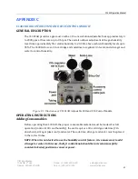
The CI-301AD requires 12V DC for operation. Refer to A-4 and figure A-7 to connect the power
supply to the connector marked “12V DC” on the CI
-301AD controller unit front panel. Remove
all
moisture on the controller panel. Plug the power connector to the jack marked “12V DC” on
the panel.
Before operation, connect the “OUT” port on the CI
-
301AD to the “INTAKE” port on the CI
-340
(see Figure C-1). Adjust both control knobs to their minimum (fully counterclockwise)
positions.
Summary of Contents for CI-340
Page 3: ......

