CI-340 Operation Manual
CID Bio-Science
1554 NE 3
rd
Ave
Camas, WA 98607, USA
Phone: +1 (360) 833-8835
Fax: +1 (360) 833-1914
[email protected]
www.cid-inc.com
38
•
Do not open or break the seal on the instrument. Under any conditions that require attention
internally, immediately contact the nearest representative or manufacturer to assist you.
LEAF CHAMBER CARE AND USE
The leaf chambers are designed to be interchangeable with the CI-340. Any of the closed or open
system chambers can be used with ease and reliability. The leaf chambers should receive the same
care and attention as is recommended for the CI-340.
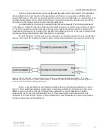
When attaching a chamber (see Figure 9-1) to the instrument, check that the O-rings (black, rubbery
rings) are in place on the connecting tubes of the chamber. Although the O-rings are not permanently
fixed on the tubes, they play an important part of assuring a better seal to the interconnecting CI-340.
A chamber without O-rings on the tubes may demonstrate leakage at the CI-340 connection.
To attach the chamber to the CI-340, carefully slide the tubes on the chamber into the “head” end of
the instrument, aligning the locking screw (from the CI-340) with the mating hole in the chamber.
Turn the locking screw to fasten the chamber to the CI-340, without over-tightening. This assures a
good lock and maximizes contact area for electrical connection between the chamber and the
instrument. The instrument may be kept on; however, do not start measurements without first
attaching a chamber.
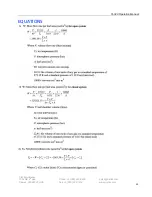
Furthermore, the IR Temperature sensor and PAR sensor should be inserted into their respective
locations on the chamber (see Figure 9-2). Check that the IR Temperature sensor is plugged securely
(without bending the tiny wire by the sensor lens) and the PAR sensor is firmly slid in to acquire ideal
measurement conditions. Connect the IR Temperature sensor and PAR sensor plugs into their
respective locations on the “head” end of the CI-340. The IR Temperature sensor should be handled
with great care.
With the chamber attached to the CI-340, and the IR Temperature sensor and PAR sensor inserted,
the leaf chamber is ready for use. Place the sample between the seals of the chamber. Now, gently
close the chamber; it will lock into place on the sample. Once sampling is completed, push the release
head forward to open the chamber. For LC-4, 5, 7-10, the release head is located on the latch piece of
the chamber. For LC-1-3, the release head is located on the topside. To disassemble, simply reverse
the steps followed to assemble the unit
Summary of Contents for CI-340
Page 3: ......


