background image

CI-340 Operation Manual 

CID Bio-Science 
1554 NE 3

rd

 Ave  

Camas, WA 98607, USA 

Phone: +1 (360) 833-8835 
Fax: +1 (360) 833-1914                                

[email protected] 
www.cid-inc.com 


53 

APPENDIX A


CI-510CS TEMPERATURE CONTROL MODULE 

The CI-510CS Temperature Control Module consists of two components (see Figure A-1 and A-2): A 

controller and Temperature Control Attachment. The CI-510CS allows you to increase or decrease 

the temperature ±25°C from ambient temperature. 

CAUTION: Avoid any obstruction or contact with the fan guards, especially small objects and 

fingers. 


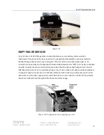
Figure A-1:  The front panel of the CI-510CS Temperature Control Module Controller 


  Figure A-2. Temperature Control Attachment, Electrical connector and Hoses. 


Figure A-3. Water connection tubing / hose


Summary of Contents for CI-340

Page 1: ...System Setup and Calibration 12 Calendar and Time Setup 13 Leaf Air Temperature Sensor 13 Atmospheric Pressure 13 Flow Rate 14 CO2 and H2O General Overview 15 CO2 Zero and CO2 Span Procedure 17 H2O Ze...

Page 2: ...t 49 Leaf Temperature Measurement 49 POWER PACK 50 ACCESSORY CONTROL PORT AND CABLE 51 TROUBLESHOOTING 52 Technical Support 52 Customer Service 52 FAQs 52 APPENDIX A 53 CI 510CS TEMPERATURE CONTROL MO...

Page 3: ......

Page 4: ...sections Table 1 Several different functions of the CI 340 with descriptions of each measurement Function Description Photosynthesis Rate Rate at which a known area of leaf assimilates CO2 over time...

Page 5: ...otosynthesis is important in comparing and understanding productivity and biomass accumulation at the leaf plant and community canopy level as well as in quantifying plant response to environmental st...

Page 6: ...sample passing a solid state CO2 analyzer The output of the analyzer is amplified sampled by an analog to digital A D converter and sent to the microprocessor The processor averages these readings and...

Page 7: ...operation of all the components to produce stable and accurate photosynthetic measurements Components include the gas exchange or leaf chamber the infrared gas analyzer the pump and mass airflow sens...

Page 8: ...the equations are based on differentials With fewer components involved there are fewer errors and less instrument drift The CI 340 can measure chlorophyll fluorescence and photosynthesis simultaneous...

Page 9: ...CI 340 Operation Manual rev 6 7 2017 CID Bio Science 1554 NE 3rd Ave Camas WA 98607 USA Phone 1 360 833 8835 Fax 1 360 833 1914 sales cid inc com www cid inc com 6 Figure 2 Parts of the CI 340...

Page 10: ...lize itself The actual measurement starts when the display changes from Working 3 Variations in the CO2 readings or Pn readings can often be caused by changes in the air stream going into the instrume...

Page 11: ...gned to emulate the familiar DOS of personal computers Note that this menu will not be accessible when there are no files stored in memory the message no files on the top display line will be briefly...

Page 12: ...rest representative or manufacturer if the included system does not include one or more of the above items If the rechargeable battery should ever fail to charge properly please recycle it Many waste...

Page 13: ...ration Manual CID Bio Science 1554 NE 3rd Ave Camas WA 98607 USA Phone 1 360 833 8835 Fax 1 360 833 1914 sales cid inc com www cid inc com 10 Figure 4 Battery installation Press the battery toward the...

Page 14: ...perature sensor in C C Leaf Stomatal conductance mmol m2 s Internal T Temperature of the analyzer environment in C E Transpiration Rate mmol m2 s EXIT to quit Aborts current operating function to the...

Page 15: ...a brief warm up time the instrument will display the basic display as follows Fri 12 Mar 2004 16 06 38 CI 340 version 5 004 Copyright CID Inc 1997 2004 All rights reserved The following screens are a...

Page 16: ...of choice With the time function set the date function will follow Once again use the or keys followed by the or keys to adjust and move to the month day and year of choice Press the key to save your...

Page 17: ...eter setup to measure flow rate The flow meter is calibrated by the manufacturer but can be calibrated again by the user Suggested calibration schedule is once every six months Scroll to choose the Ca...

Page 18: ...termine the humidity temperature of the gas NOTE For greater changes in ambient temperatures between sample measurements it may be necessary to recalibrate to CO2 zero setting at each temperature i e...

Page 19: ...lection The system will then return to the following screen display and reset ENTER to select Calibrate CO2 H2O calibration follows similar procedures Dry nitrogen gas or silicon gel Figure 8 can be u...

Page 20: ...ing Silica Gel for H2O calibration CO2 Zero and CO2 Span Procedure Tools required CI 340 Soda Lime external conditioning tube filter hose barbs a CO2 standard gas ranging from 200 1000 ppm a t junctio...

Page 21: ...se known CO2 gas Press START ENTER 8 To only calibrate the CO2 zero press EXIT and you are done To continue on and calibrate the CO2 span hit start enter 9 If you pressed start enter connect a standar...

Page 22: ...ish to calibrate the H2O zero press EXIT 7 To calibrate the H2O span connect a gas with a known concentration of H2O see general overview a Press Start Enter b The unit will display H2O pressure x xxx...

Page 23: ...lecting instrument is its portability The CI 340 is almost a small user friendly computer that can be operated almost anywhere in the field However data analysis and presentation can best be done on a...

Page 24: ...CI 340 program files It is the best to copy all the software files provided on the disk to their own directory on the hard drive before executing DL exe Connect the CI 340 USB cable Run the DL exe pro...

Page 25: ...3 12 3 27 35 1 37 2 325 0 03 8 3 6 59 38 13 1 2 78 2 16 35 4 36 9 310 5 03 8 3 6 59 48 21 6 2 66 1 54 35 3 37 310 0 03 8 3 6 59 58 Where Internal T Internal temperature for the instrument Flow Flow ra...

Page 26: ...The CI 340 is designed so that measurements can incorporate both absolute and differential readings simultaneously This instrument can also be configured to operate both open and closed systems It is...

Page 27: ...mber values o Note that the symbols etc in the keys are not recognized if naming a file and in turn will show up as the respective number key Press the key to continue to the time interval setup The k...

Page 28: ...lations for photosynthesis transmission or stomatal conductance rates The allotted range is 001 10 000 cm2 If the leaf you are using fully covers the leaf chamber window enter the area of the window T...

Page 29: ...ment provides another practical method to determine photosynthesis transpiration and stomatal conductance The physical distinction between the two systems is with the accessory tubing attachment Figur...

Page 30: ...er for proper applications of the leaf chamber s Then press the or and key s to begin the measurement process Table 2 Open system chamber sizes Chamber Types Window Size W x L mm Window Area cm2 Squar...

Page 31: ...chamber environment and the instrument intake Almost all commercial plant IRGA systems are of the differential type because they provide more reliable measurements The CI 340 is capable of obtaining...

Page 32: ...er with the number of photons than with energy This is expected because photosynthesis is a photochemical conversion where each molecule is activated by the absorption of one photon in the primary pho...

Page 33: ...occurs and the stomata close immediately reducing the rate of transpiration as well as the rate of photosynthesis Stomatal Conductance Stomatal conductance is water loss by a leaf and is directly rel...

Page 34: ...The change in CO2 and H2O concentrations per unit of time are correlated with net photosynthesis assimilation and transpiration respectively The leaf chambers for closed system measurements are specia...

Page 35: ...ype Window Size W x L mm Window Area cm2 CI 301 Square 25 x 25 6 25 LC 1 Narrow Rectangular 65 x 10 6 25 LC 3 Wide Rectangular 55 x 20 11 LC 2 Small Cylindrical 25 x 90 22 5 LC 4 Large Cylindrical 50...

Page 36: ...x length 25 mm x 90 mm Window area 22 5 cm2 Diameter of chamber 2 cm Maximum diameter of branch 0 5 cm Maximum diameter of branch and needles 2 cm LC 5 Large Cylinder Chamber Specifications Window siz...

Page 37: ...t half 50 of the window on the upper surface of the leaf chamber Next apply this percentage to the size of the entire window area 6 5 cm2 The leaf area entered into the CI 340 should be approximately...

Page 38: ...um reliability as well as ease of instrument use in the field The resolution of infrared gas analyzers is directly related to the length of the infrared gas analyzer chamber The longer the tube to the...

Page 39: ...ent hardware It is best used for large sample data With the use of the CI 510LA CI 301LA the response curve of photosynthesis vs light can be seen by pressing L when measuring photosynthesis that is s...

Page 40: ...r changes to the controlled parameters It will also erase the graph The tick marks at the left of the screen while in graph mode represent 5 molm 2 s 1 CARE OF THE CI 340 This instrument is designed f...

Page 41: ...the mating hole in the chamber Turn the locking screw to fasten the chamber to the CI 340 without over tightening This assures a good lock and maximizes contact area for electrical connection between...

Page 42: ...com 39 Figure 9 1 llustration of a leaf chamber CI 301LC 2 Wide Rectangular Chamber for an open system We recommend working in temperature ranges between 5 and 45 C for greatest precision Be sure bot...

Page 43: ...I 340 Operation Manual CID Bio Science 1554 NE 3rd Ave Camas WA 98607 USA Phone 1 360 833 8835 Fax 1 360 833 1914 sales cid inc com www cid inc com 40 Figure 9 2 Connecting a leaf chamber to the CI 34...

Page 44: ...pproximate five minutes of use remaining before the instrument shuts down When operating the instrument at colder temperatures below 5o C the battery will diminish in performance Batteries should be f...

Page 45: ...2 2 Plug the power cable into a lab power socket 3 Attach the Li ion Battery to the charger adapter Align the front end of the Li ion Battery with the guides on the charger adapter then press and slid...

Page 46: ...adapters for overseas use To prevent equipment breakdowns and excessive heating do not connect this charger adapter to voltage converters used by travelers or special power sources such as on aircraf...

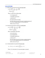
Page 47: ...CI 340 Operation Manual CID Bio Science 1554 NE 3rd Ave Camas WA 98607 USA Phone 1 360 833 8835 Fax 1 360 833 1914 sales cid inc com www cid inc com 44 EQUATIONS...

Page 48: ...CI 340 Operation Manual CID Bio Science 1554 NE 3rd Ave Camas WA 98607 USA Phone 1 360 833 8835 Fax 1 360 833 1914 sales cid inc com www cid inc com 45...

Page 49: ...instrument or simply unplug the cable connector The switch should only be in the ON position away from the instrument when downloading codes from a computer Display does not come on after continuous...

Page 50: ...measuring environment should be appropriately sealed by the chamber head so that the intended sample is analyzed accurately The sample s may not be a good source Ambient internal operating temperature...

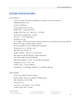
Page 51: ...ontinuous use extended hours of use with additional batteries AC Adapter Battery Charger supplied Power consumption 2 5 watts sample pump in operation Pump flow rate 100 1000 cm2 min Mass flow meter A...

Page 52: ...a 0 5V signal for 50 RH which is amplified to 2 34V and measured with a 16bit ADC PAR Sensor Sensor Type Filtered GaAsP photodiode Range 0 2500 mol m 2 s 1 Accuracy 5 mol 0 2500 mol m2 sec Response 4...

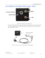
Page 53: ...e connections for optional modules If you have all four modules the power cable should be plugged in during operation Figure 14 3 If you do not have all four modules there will be foam spacers in the...

Page 54: ...SSORY CONTROL PORT AND CABLE Figure 14 4 CI 340 Accessory Control Port The colored jacks on the accessory control cable Figure 14 5 indicate the accessory module to plug into The red plug goes to the...

Page 55: ...ase use the serial number of your instrument as the subject line of the email CID Bio Science Inc s contact information CID Bio Science Inc 1554 NE 3rd Ave Camas WA 98607 USA Phone 800 767 0119 U S an...

Page 56: ...ents see Figure A 1 and A 2 A controller and Temperature Control Attachment The CI 510CS allows you to increase or decrease the temperature 25 C from ambient temperature CAUTION Avoid any obstruction...

Page 57: ...Turn the power on and observe the flow of water so that water steadily exits the other hose connection from the Temperature Control Attachment Once a steady flow of water has been established air bubb...

Page 58: ...the controller panel open to air Connect one hose from the Temperature Control Attachment to the OUT port on the controller module Connect the water connection tube to the other hose from the Tempera...

Page 59: ...trol Attachment with the threaded holes on the chamber bottom and tighten using the Allen wrench provided see Figure A 7 The Infrared Leaf Temperature sensor should be inserted into the respective hol...

Page 60: ...mer state with the Temperature knob You can vary the setting according to the readout of your CI 340 Photosynthesis System There is a Remote Input socket on the Controller panel This can be used by re...

Page 61: ...ith cooling fans which have exhaust vents along the sides and intake vents on the bottom Keep these vents clear at all times during use to avoid overheating Refer to A 1 in APPENDIX A to connect the p...

Page 62: ...cid inc com 59 A small cable with a plug connected to the lamp is the PAR sensing output Make sure that the lamp covers the chamber window area so the PAR intensity emitted from the lamp or the extern...

Page 63: ...1914 sales cid inc com www cid inc com 60 REMINDER The CI 301LA Light Attachment intake and exhaust vents must remain unobstructed during use to avoid overheating and possible damage to the light sou...

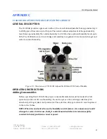
Page 64: ...uses a CO2 cartridge and soda lime to regulate CO2 levels and silica gel and water to control humidity Figure C 1 Illustration of CI 301AD Adjustable H2O and CO2 Control Module OPERATING INSTRUCTIONS...

Page 65: ...l the water tube remove the top cap in the same manner The caps will come off along with an internal assembly This assembly deflects water bubbles from entering the system during operation You will no...

Page 66: ...from the CI 301AD into the analyzer system An external pump may be required if using a different analyzer Do not attempt to draw more than 0 5 LPM liter per minute from the CI 301AD output Doing so m...

Page 67: ...onnected to the CI 340 and the yellow color coded plug must be inserted into the remote control jack of the CI 301AD Turn the CO2 knob fully counterclockwise and the H2O knob fully clockwise REPLACING...

Page 68: ...ted into the silica gel may not function properly after this process even though the silica gel itself may be dry Water Water should be added if the level falls significantly Change the water if it be...

Page 69: ...te the chamber slightly to ensure that the cylinder is seated into the surface of the soil a good seal is important to obtain accurate readings If you need PAR readings check so that the PAR sensor is...

Page 70: ...eration Manual CID Bio Science 1554 NE 3rd Ave Camas WA 98607 USA Phone 1 360 833 8835 Fax 1 360 833 1914 sales cid inc com www cid inc com 67 Figure D 1 Configuration for the CI 301SR Soil Respiratio...

Page 71: ...ambient light intensity To prepare for measurements align Attachment A and Attachment B with the seals facing the enclosure With this alignment the tubes in Attachment A should slide into the respect...

Page 72: ...ze of plant or study area The canopy chamber is a closed system and air is not renewed inside of the chamber during analysis Extremely large chambers have several limitations in the field such as that...

Page 73: ...uld slide into the respective holes in the inside piece Secure the entire canopy chamber attachment onto the enclosure by tightening the thumbscrews on the inside piece Attaching Chamber to the CI 340...

Page 74: ...hosen The flow rate should be doubled or increased from the default of 0 3 lpm to 0 6 lpm When using the canopy chamber only the single fan in the analyzer controls air flow since there is no separate...

Page 75: ...d inc com www cid inc com 72 Figure E 1 Configuration for the Canopy Chamber Attachment A rigid wall plant canopy chamber attaching to the CI 340 The PAR sensor can either be attached to the canopy ch...

Page 76: ...nnector and another end with four plugs is used for communication between the CI 340 instrument and the CI 510CF module Connect the eight pin connector of the Accessory control cable to the Accessory...

Page 77: ...s ambient Ratio of DHL H Fv Fm dark Y ambient The Ratio is the only value that is not in A D counts It should be interpreted as 0 xxx where xxx is the number displayed in the table For example if the...

Page 78: ...nc com www cid inc com 75 A D converter 2000 counts Measured parameters Chlorophyll fluorescence trace data Fo Fm Fv Fm dark adapted Fs Fms Y ambient illumination Modulated light intensity 0 25 uE at...

Page 79: ...uipment which is not manufactured by CID Bio Science is to be covered only by the warranty of its manufacturer CID Bio Science will not be liable to the Buyer for loss damage or injury to persons or t...

Reviews: