F6.15
F6.15
6.1 Schedule of Function Parameters
6.1 Schedule of Function Parameters
F6.09 Sampling period T Setting range: 0.01~10.00s Default value: 0.00s
Sampling period refers to the cycle in which the system conducts sampling over
feedback quantity. PID regulator
calculation in each period of sampling
and gets the output value of PID regulation. The longer the sampling period is, the
slower the response is. If F6.09=0.00, the sampling period will be finished
automatically.
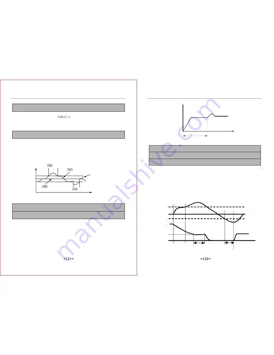
F6.10 Deviation limit Setting range: 0.0~20.0% Default value: 0.0%
Deviation limit refers to the maximum value of deviation between feedback quantity
and set quantity within allowable range of the system. When the difference
(modulus) between feedback quantity and set quantity is lower than this set
parameter value, PID controller will be disabled, as shown in Fig. 6-23.
Proper setting of this parameter is of advantage to improve the stability of the output
of system which needs to avoid frequent regulation though it has no high
requirement on control precision.
Frequency
Action
Action
Feedback
Set
Deviation limit
Time
Fig.6-23 Diagram of Deviation Limit Function
F6.11 Closed loop preset frequency Setting range: 0.00~upper limit frequency
Default value: 0.00Hz
F6.12 Closed loop preset frequency holding time Setting range: 0.0~6000.0s
Default value: 0.0s
This parameter defines the inverter's pre-operation frequency and operation time
before PID puts into real operation when PID control is enabled. In some control
systems, the inverter shall output forcefully a certain frequency value F6.11 to the
preset time F6.12 according to this parameter setting so that the controlled object
will reach the preset value instantly. PID controller will not put into use until the
controlled object approaches the controlling object to raise response speed, as shown
in Fig.6-24.
Output
frequency
Preset frequency
Preset frequency
holding time
Time
F6.13 Sleep threshold Setting range: 0.00~10.00V Default value: 10.00V
F6.14 Wake-up threshold Setting range: 0.00~10.00V Default value: 0.00V
Fig.6-24 Closed Loop Preset Frequency Operation Diagram
F6.13 indicates the pressure limit of water supply system in the state of sleep.
When network pressure is higher than this setting value and the frequency changing
the water supply system isadjusted to run at lower frequency, the inverter will
automatically enter into the state of sleep (zero speed running) through F6.15.
and wait for wake-up.
F6.14 indicates the pressure limit of water supply system when it enters into
working state from sleeping state.
When network pressure is lower than the setting value,After the inverter pass
the delay time through F6.15. the frequency changing water supply system will
automatically shift to working state from sleeping state .as shown in Fig.6-25.
PID feedback
Sleep threshold
PID setting
Output frequency
Wake-up threshold
Sleep
Wake-up
Lower limit frequency
Fig.6-25 Sleep and wake-up function Diagram
F6.15 Sleep/ Wake up threshold value check-out time Setting Range:0.0~600.0s Default value:300.0s
Summary of Contents for ZVF9V-G/P
Page 8: ...M Integration Module S Schism Module...
Page 12: ......
Page 16: ......
Page 21: ...Inverter...
Page 33: ......
Page 87: ......


