6.1 Schedule of Function Parameters
6.1 Schedule of Function Parameters
4
Acceleration/Deceleration time 1 5: Acceleration/Deceleration time 2
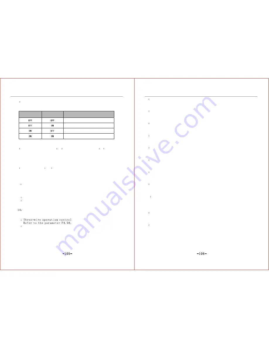
It is used for external terminal's selection of acceleration/deceleration time,
which has four combined groups as shown in Table 6-3.
Acceleration/
Deceleration time 2
Acceleration/
Deceleration time 1
Multi-stage speed selection
Acceleration/Deceleration time 1
Acceleration/Deceleration time 2
Acceleration/Deceleration time 3
Acceleration/Deceleration time 4
Table 6-3 Acceleration/Deceleration Time Selection
6
Frequency path selection 1
7
Frequency path selection 2
8
Frequency
path selection 3
If frequency input path is external terminal selection (F0.01=8), the inverter's
frequency setting path is determined by the state of three terminals. Refer to
Table 6-1 for correlation.
9
FRD JOG control 10
REV JOG control
9 and 10 are used to perform FRD/REV JOG control in the mode of external
terminal control. FRD JOG control is always prior to REV JOG control. If they
close simultaneously, then FRD JOG control is valid.
11
Free stop control
This is used to free stop control under the mode of external terminal control. The
inverter will perform free stop when it is closed and start in the mode of rotation
speed tracking when it is open.
12
Frequency UP Command
13
Frequency DOWN Command
Commands of 12 and 13 are used to realize control over frequency up or down,
and proceed remote control through operator panel.
External Failure Input
This terminal paves the way for the inverter to keep an eye on external
equipment failure by inputting failure signals of external equipment.
15
16
DC braking command
DC braking command is used to apply DC braking on the motor during stop, to
realize emergency shut-down and accurate positioning of the motor. See the
parameter F2.12~F2.14 for details.
17
Counter zero-clearance input
Once this function is set, connect this terminal with COM terminal and the counter
value will be "0".
18
Counter pulse signal input
This is used to receive external pulse signal which is served as the count value.
This function can be set only by the multifunction terminal X6.
19
External pulse signal input
This is used to receive external pulse signal which is served as frequency setting.
This function can be set only by the multifunction terminal X6.
20
External reset input
When failure alarm occurs, this terminal is used to perform failure reset of the
inverter. This function is in accord with STOP key on the operator panel.
21
UP/DOWN terminal frequency clear
If frequency feeding path is set to UP/DOWN terminal control that are valid, then the operation
frequency can be removed directly through this function.
22
PID operation input
When PID input mode is terminal control, PID operation will be valid if this
terminal is valid.
23
Programmable multi-stage speed operation input
When the input mode of programmable multi-stage speed operation (PLC) is
terminal control, PLC input operation will be valid if this terminal is valid.
24
Wobble operation input
When the wobble input mode is terminal control, the wobble operation will be
valid if this terminal is valid.
25
Wobble state reset
If this function is selected, no matter what kind of input it is, auto or hand-
operated, close this terminal, the wobble state info kept inside the inverter will be
cleared; disconnect this terminal, the wobble will restart.
26
External stop command
This command is valid for all the operation command paths. If this terminal is
valid, the inverter will shut down according to the mode set by F2.11.
27
Inverter operation disable command
If this terminal is valid, the inverter in operation will perform free stop. If the
inverter is in the state of halting, then starting is disabled. This function is mainly
applied to the occasion that safe linking is needed.
Summary of Contents for ZVF9V-G/P
Page 8: ...M Integration Module S Schism Module...
Page 12: ......
Page 16: ......
Page 21: ...Inverter...
Page 33: ......
Page 87: ......


