6.1 Schedule of Function Parameters
6.1 Schedule of Function Parameters
F2.06 S curve initial stage time percentage Setting range: 10.0~40.0%
Default value: 20.0%
2.07 S curve rise/fall stage time percentage Setting range: 10.0~80.0%
Default value: 60.0%
S curve initial stage, as shown in Fig.6-8, is the course during which the slope of output frequency
gradually increases from 0.
S curve rise stage, as shown in Fig.6-8, is the stage that the slop of output frequency remains
constant.
Combined using of the above parameters, is particularly applied to start or stop of loads during
delivery or move.
F2.08 AVR function selection Setting range: 0 ~ 1 Default value: 1
0
Disabled
1
Enabled
AVR means automatic voltage regulation. When deviation occurs between input
voltage and rated input voltage of the inverter, this function is applied to stabilize
the output voltage of the inverter through auto regulation of duty factor of PWM.
This function is invalid if the output command voltage is higher than the input
power supply voltage. During deceleration, if AVR function is disabled, the
deceleration time will be short but the operation current will be bigger; if AVR is
enabled, the motor will decelerate steadily but the operation current will be
smaller.
F2.09 Selection of automatic energy-saving operation Setting range: 0~1 Default value: 0
When selecting automatic energy-saving operation, the inverter will automatically
regulate the motor's output voltage by detecting the load current, so as to get
minimum product (electric power ) of voltage and current and realize energy saving.
0
Disabled 1
Enabled
This function is applicable to loads like fans,
water pumps and etc.
Automatic energy-saving operation is invalid during
acceleration and deceleration.
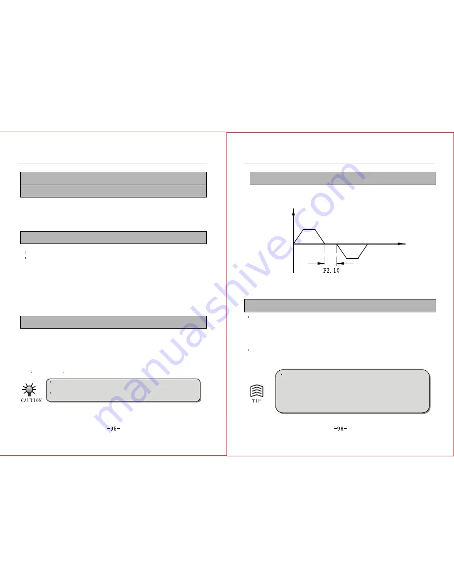
F2.10 FRD/REV Dead Time Setting range: 0.0~10.0s Default value: 0.0s
This indicates the interval between FRD and REV when the inverter transfers from
forward running to 0.00Hz then to reverse running; or from reverse running to
0.00Hz then to forward running, as shown in Fig.6-9.
Frequency
Time
Fig.6-9 FRD/REV Dead Time
F2.11 Stop mode selection Setting range: 0~1 Default value: 0
0
Decelerating stop
When stop command is received, the inverter will drop off output frequency in
accordance with the set decelerating mode and decelerating time till the frequency falls
to zero and stop. If DC braking function is selected, then the inverter will begin braking
when the frequency reaches the braking initial frequency and shut down after DC braking
is accomplished.
1
Free stop
Once stop command is received, the inverter will discard output immediately and the
load will stop freely in accordance with the rule of mechanical inertia.
If decelerating stop (F2.11=0) is selected, the inverter will discard output
upon receiving of stop command. When the motor decelerates to the
shutdown DC braking starting frequency
(F2.12)
(which indicates the
inverter's starting frequency when the motor is shutdown by DC braking), the
inverter will stop by braking according to
shutdown DC braking voltage
(which indicates the inverter's voltage when the motor is shutdown by DC
braking) set by F2.13 and
shutdown DC braking time
(which indicates a
specified period of time used to stop the motor by DC braking) set by F2.14.
Summary of Contents for ZVF9V-G/P
Page 8: ...M Integration Module S Schism Module...
Page 12: ......
Page 16: ......
Page 21: ...Inverter...
Page 33: ......
Page 87: ......


