background image

Format

Cables

Frame rate (Hz)

Sampling

Bit-depth

Notes

(St 2082-12)
mode 2 structure
IV

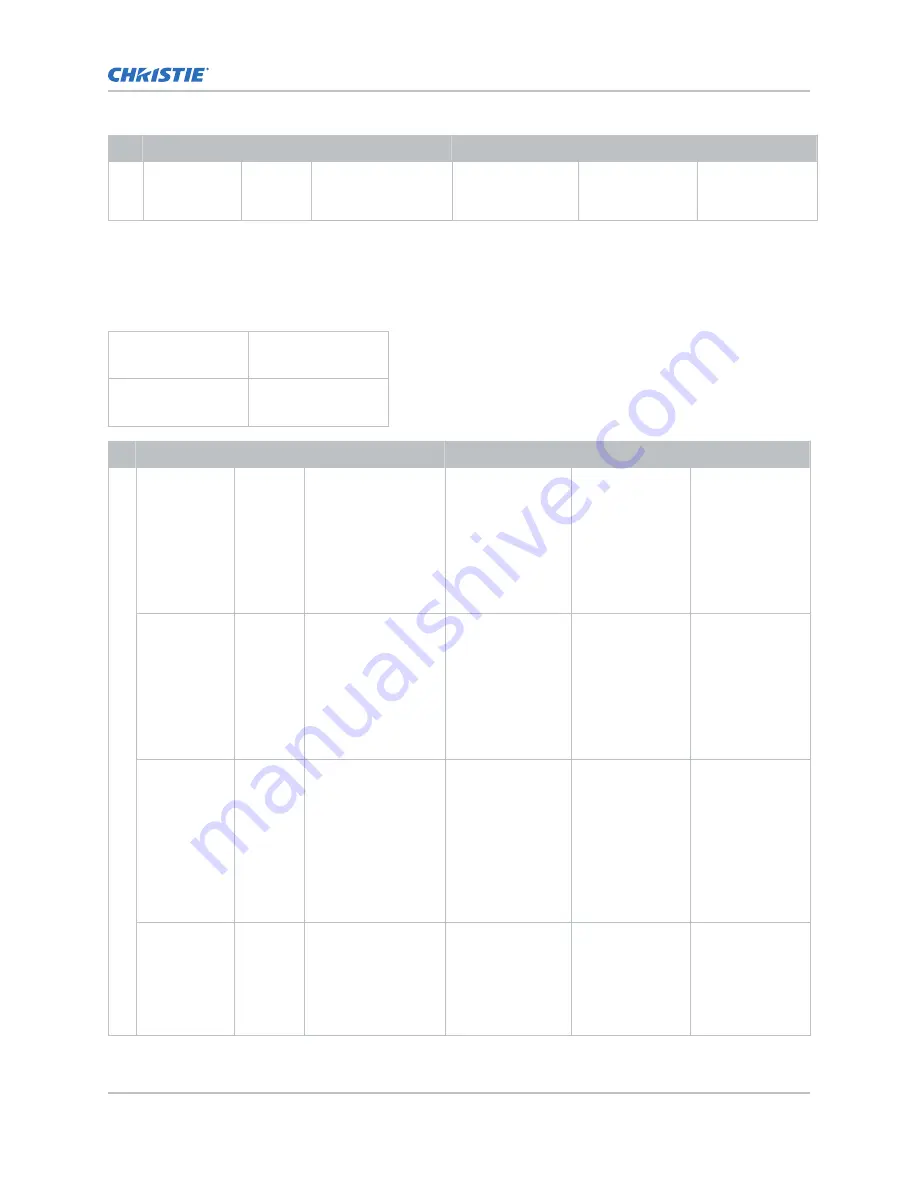
Quad-link square-division 2D image formats

The following quad-link 2D SDI image formats are supported in square division mapping format, so
each SDI input shall represent one quarter of the total image assigned as shown in the following
diagram:

Input 1
SDI 1

Input 2
SDI 2

Input 3
SDI 3

Input 4
SDI 4

Format

Cables

Frame rate (Hz)

Sampling

Bit-depth

Notes

4K 3840x2160

4

24, 25, 30

Y'C'

B

C'

R

/RGB/

4:4:4:(4)

10bpc

Y'C'

B

C'

R

/RGB

component at
quad-link 3Gb/s
(ST 425-5) annex
B square division
of 2160-image
formats, B.1 level
A mapping

3840x2160

4

24, 25, 30

Y'C'

B

C'

R

/RGB/

4:4:4

12bpc

Y'C'

B

C'

R

/RGB

component at
quad-link 3Gb/s
(ST 425-5) annex
B square division
of 2160-image
formats, B.1 level
A mapping

3840x2160

4

24, 25, 30

Y'C'

B

C'

R

/4:2:2:4

12bpc

Y'C'

B

C'

R

component at
quad-link 3Gb/s
(ST 425-5)
structure annex B
square division of
2160-image
formats B.1 level
A mapping

3840x2160

4

24, 25, 30

Y'C'

B

C'

R

/4:2:2

12bpc

Y'C'

B

C'

R

component at
quad-link 3Gb/s
(ST 425-5)
structure annex B
square division of

Video Input panel

C User Guide–CP4415-RGB, CP4420-RGB, CP4435-RGB, CP4440-RGB, CP4450-RGB, CP2420-Xe, CP4420-Xe

37

020-103073-06 Rev. 1 (03-2022)

Copyright 

©

 2022 Christie Digital Systems USA, Inc. All rights reserved.

Summary of Contents for CineLife+

Page 1: ...User Guide 020 103073 06 CineLife CP4415 RGB CP4420 RGB CP4435 RGB CP4440 RGB CP4450 RGB CP2420 Xe CP4420 Xe...

Page 2: ...tie dealer or Christie PREVENTATIVE MAINTENANCE Preventative maintenance is an important part of the continued and proper operation of your product Failure to perform maintenance as required and in ac...

Page 3: ...Remote user interface UI 17 Turning the touch panel on or off 18 Understanding the Christie touch panel interface and remote user interface 18 Turning the light source on or off 19 Opening or closing...

Page 4: ...sensor to screen calibration Workflow 49 Creating a new calibration file 50 Recalibrating an existing calibration file 51 Editing the existing calibration file parameters 52 Verifying the sensor to s...

Page 5: ...l for IMB input 65 Adding a channel for SDI input 67 Selecting the active channel 68 Editing an existing channel 68 Copying existing channel settings to a new channel 68 Viewing the channel list 69 Mo...

Page 6: ...tivating a warp file 78 Adjusting the image 80 Correcting vignetting 80 Correcting keystone effect 80 Adjusting the integrator rod and fold mirror 81 Adjusting boresight 84 Adjusting DMD convergence 8...

Page 7: ...eating editing and deleting playlist triggers 103 Creating a new global trigger 103 Editing existing global trigger settings 103 Deleting a global trigger 103 Importing a device library 103 Viewing a...

Page 8: ...ding a certificate 109 Regulatory 110 Safety 110 Electro magnetic compatibility 110 Emissions 110 Immunity 110 Environmental 111 Content CineLife User Guide CP4415 RGB CP4420 RGB CP4435 RGB CP4440 RGB...

Page 9: ...entation available on the Christie website Read all instructions before using or servicing this product 1 Access the documentation from the Christie website Go to this URL https bit ly 3lkZ48l or http...

Page 10: ...ment must be used to position the product Do not install or operate the projector in any position that does not meet the stated product specifications for alignment and orientation Caution If not avoi...

Page 11: ...clothing gloves jacket face shield whenever the lamp door is open or when handling the lamp Any local or federal specifications take precedence over Christie s protective clothing recommendations Do n...

Page 12: ...of space where the projection light from the laser illuminated projector is above emission limits for Risk Group 2 The light intensity may cause eye damage after a momentary or brief exposure before a...

Page 13: ...sory box with the manual Certain US states have additional laser regulatory requirements Contact lasercompliance christiedigital com for additional regulatory requirements Technical support Technical...

Page 14: ...f Power is available to the optional touch panel and laser optical sub systems LOS Power is available to the thermo electric cooler TEC devices however the drivers are disabled Some fans are low speed...

Page 15: ...verify the chiller communication cables are connected correctly between each projector chiller pair This ensures no cross connection exists relative to the coolant lines Turning the projector on or of...

Page 16: ...5 seconds The projector turns on the light source and displays a test pattern with the projector s IP address and any currently active alarms Resetting the projector IP address to the default Use the...

Page 17: ...e the File Menu Examples of items that can be uploaded include Projector upgrade packages Backup packages to restore from Rental files to license the projector for Rental mode Test patterns PNG files...

Page 18: ...terface Use the touch panel to control the projector and perform functions such as turning the light on or off selecting channels and viewing status information If no touch panel is installed use the...

Page 19: ...rns the projector on or off Turning the light source on or off Turn the light source on to display content or view test patterns Turn the light off to extend the life of the light source To turn the l...

Page 20: ...nonfunctional To avoid damage to the projector only enable this option when the shutter can be verified as open Adding a network time protocol server Add a network time protocol NTP server to synchron...

Page 21: ...ne tab 3 In the Region list select a region 4 In the Time Zone list select the time zone 5 Select Save Changing the time format You can use the 12 hour or 24 hour format to display projector time The...

Page 22: ...ation see the CineLife 4K RGB Installation and Setup Guide P N 020 103244 XX Normal Rear Projection from behind the screen with the projector in the normal upright position Inverted Rear Projection fr...

Page 23: ...k when in this mode Solid yellow Standby mode Power is off lamp is off Power saving mode Flashing yellow and then green intermittently Cool down mode Power is on lamp is off The lamp may be struck whe...

Page 24: ...Micro BNC Connector Multi Rate SDI in accordance with SMPTE ST 259 270Mb s ST 292 1 1 5Gb s ST 424 3 0Gb s ST 2081 1 6Gb s and ST 2082 1 12Gb s C DisplayPort DP1 and DP2 Accepts digital video data fr...

Page 25: ...ces N 3D sync connector Connects the projector to 3D devices HDMI video source For the projector to accept digital video data from HDMI sources plug the HDMI source directly into the Video Input panel...

Page 26: ...pling Bit depth Notes HD 1280x720 1 24 25 30 50 60 Y C BC R RGB 4 4 4 Y CBCR 4 2 2 8 10 12bpc 1920x1080i 1 25 30 Y C BC R RGB 4 4 4 Y CBCR 4 2 2 8 10 12bpc 2048x1080 interlaced 50 60 Hz field rate Sin...

Page 27: ...listed below are supported Input configuration Description Single link Accepts connection of 12G 6G 3G and HD SD SDI input standards Dual link Accepts connection of dual link 6G 3G and HD SDI input s...

Page 28: ...Y C BC R RGB component at 6 0Gb s ST 2081 10 structure II 1920X1080 1 48 50 60 Y C BC R RGB 4 4 4 12bpc HD 1080p Y C BC R RGB component at 6 0Gb s ST 2081 10 mode 2 structure III 4K 3840x2160 1 24 25...

Page 29: ...link one cable 2D SD 720p and 1080i image formats Format Frame rate Hz Sampling Bit depth Notes SD 720x480 60 Y C BC R 4 2 2 10bpc SD interlaced component at 270Mb s ST 259 level C interlaced 60 Hz f...

Page 30: ...Y C BC R component at 6 0Gb s ST 2081 10 mode 3 1920x1080 1 96 100 120 Y C BC R RGB 4 4 4 4 10bpc HD 1080p Y C BC R GB component at 12 0Gb s ST 2082 10 mode 2 structure II 1920x1080 1 96 100 120 Y C...

Page 31: ...4 12bpc HD 1080p YCbCr component at 3 0Gb s ST 425 1 level A 1920x1080 2 48 50 60 Y C BC R RGB 4 4 4 4 10bpc HD 1080p Y C BC R RGB component at 6 0Gb s ST 2081 10 structure II 1920X1080 2 48 50 60 Y...

Page 32: ...able 2D SDI input formats are supported Input 1 SDI 1 and SDI 2 Input 1 SDI 1 and SDI 2 Format Cables Frame rate Hz Sampling Bit depth Notes HD 1920x1080 2 48 50 60 Y C BC R RGB 4 4 4 4 10bpc Y C BC R...

Page 33: ...dual link 6Gb s ST 2081 11 mode 1 3840x2160 2 24 25 30 Y C BC R 4 2 2 12bpc Y C BC R component at dual link 6Gb s ST 2081 11 mode 1 3840x2160 2 24 25 30 Y C BC R 4 2 2 4 Y C BC R component at dual lin...

Page 34: ...4 2 2 12bpc Y C BC R component at dual link 3Gb s ST 425 3 structure IV 1920x1080 4 48 50 60 Y C BC R 4 2 2 4 12bpc Y C BC R component at dual link 3Gb s ST 425 3 structure IV 4K 3840x2160 4 24 25 30...

Page 35: ...nent at quad link 3Gb s ST 425 5 structure 2 level A 3840x2160 4 24 25 30 Y C BC R RGB 4 4 4 12bpc Y C BC R RGB component at quad link 3Gb s ST 425 5 structure 3 level A 3840x2160 4 24 25 30 Y C BC R...

Page 36: ...are supported Format Cables Frame rate Hz Sampling Bit depth Notes 4K 3840x2160 4 96 100 120 Y C BC R 4 2 2 10bpc Y C BC R component at quad link 6Gb s ST 2081 12 mode 3 3840x2160 4 96 100 120 Y C BC...

Page 37: ...5 annex B square division of 2160 image formats B 1 level A mapping 3840x2160 4 24 25 30 Y C BC R RGB 4 4 4 12bpc Y C BC R RGB component at quad link 3Gb s ST 425 5 annex B square division of 2160 im...

Page 38: ...0 4 48 50 60 Y C BC R 4 2 2 4 12bpc Y C BC R component at 6Gb s ST 2081 10 mode 2 structure IV x 4 3840x2160 4 96 100 120 Y C BC R 4 2 2 10bpc Y C BC R component at 6 0Gb s ST 2081 10 mode 3 x 4 3840x...

Page 39: ...C BC R RGB 4 4 4 4 12bpc HD 1080p Y C BC R RGB component at 3 0Gb s ST 425 1 level A 1920x1080 1 24 25 30 Y C BC R 4 2 2 4 12bpc HD 1080p Y C BC R component at 3 0Gb s ST 425 1 level A 1920x1080 1 48...

Page 40: ...Video Input panel The input configurations listed below are supported Input configuration Description Single input Enables connection of one DisplayPort cable Supports both 2D and 3D frame sequential...

Page 41: ...bpc 2048x1080 1 24 25 30 50 60 Y C BC R RGB 4 4 4 8 10 12bpc 4K 3840x2160 1 24 25 30 Y C BC R RGB 4 4 4 8 10bpc 4096x2160 1 24 25 30 Y C BC R RGB 4 4 4 8 10bpc Dual input 3D DisplayPort 1 2 image form...

Page 42: ...e compatible with Christie projectors Series 2 IMB video formats S2 IMB video format support is determined by the IMB make and model Refer to the associated IMB documentation to understand which of th...

Page 43: ...1024x768 79 6 79 6 23 0 8 bits 720p HD 1280x720 68 0 68 0 23 0 8 bits 4VGA 1280x960 51 0 51 0 23 0 8 bits SXGA 1280x1024 47 8 N A 23 0 8 bits 525 16SIF 1408x960 46 3 N A 23 0 8 bits 16CIF 1408x1152 3...

Page 44: ...Y Z 4 4 4 12 bits SMPTE 2048 1 2011 Am1 2016 4096x2160 100 X Y Z 4 4 4 12 bits SMPTE 2048 1 2011 Am1 2016 4096x2160 120 X Y Z 4 4 4 12 bits SMPTE compatible cinema formats 3D JPEG 2000 image formats...

Page 45: ...ported are determined by the IMB make and model SDI video source connection from an IMB The projector can accept digital video data from SDI sources connected to applicable IMB devices The input confi...

Page 46: ...og in as service 2 Turn the laser on 3 For systems upgraded to v1 5 0 and already using the calibration file set a channel to use the appropriate calibration file on page 63 and activate the channel o...

Page 47: ...6 In the left navigation menu select Laser Settings Laser Power LiteLOC Setup 7 Select the Display White Test Pattern slider 8 To create a new laser file select Create 9 In the Create dialog type a na...

Page 48: ...nt and allow the projector to stabilize for a few minutes System stability may be affected if you set a power level below the minimum power level recommended 11 If white or brightness is not at the ta...

Page 49: ...isfied some scenarios may exist in which you may need to re do the calibration in the future Re doing this calibration is required if the following is replaced Color sensor board Christie recommends r...

Page 50: ...ns can be selected in any order The projector automatically sets the red green and blue output laser powers to the pre determined settings calculated and displayed in the Drive Percentage Calculated a...

Page 51: ...g the wizard 4 In step 1 of the Sensor to screen Calibration wizard set the maximum brightness and color point a Enable the Display White Test Pattern option b To set the maximum expected room and chi...

Page 52: ...d the measured white point must be within the expected tolerance c When complete select Finish The projector output is configured according to the currently selected calibration file and you are retur...

Page 53: ...3D Sensor to Screen Calibration File list in the Channel Setup menu By default the 2D and 3D sensor to screen calibration files are set to the factory or field calibration data identified as Default i...

Page 54: ...e projector from AC power and turn off the circuit breaker for the projector Adjusting the lamp power Learn how to adjust the lamp power 1 In the left navigation menu select Lamp Settings Lamp Power L...

Page 55: ...ce from the lens does not matter You may need an attenuator or an internal foil aperture 4 In the left navigation menu select Lamp Settings Lamp Power LiteLOC Setup 5 Select the directional arrows to...

Page 56: ...e minimum and maximum lamp power by lamp type Lamp type Lamp size Minimum lamp power Maximum lamp power Other 20 2 kW 1000W 50 2200W 110 CDXL 20 2 kW 1000W 50 2200W 110 Other 30 CXL 30 CDXL 30 CDXL 30...

Page 57: ...rmation This is the default level for serial communication sessions service Can access all user interface windows Cannot authorize projector marriage Adding a user account Adding a user account allows...

Page 58: ...nfirm Password fields 5 Select Save Deleting a user account Delete a user account to prevent access to projector menus and functionality 1 In the left navigation menu select Service Setup User Account...

Page 59: ...ption IP Address IP address of the projector Subnet Mask Subnet mask to which the IP address belongs Gateway IP address for the network gateway Primary DNS IP address of the primary DNS server Seconda...

Page 60: ...Management Information Base MIB file contains the definitions for the device being managed by the SNMP protocol 1 In the left navigation menu select Service Setup Network Settings 2 Select the SNMP ta...

Page 61: ...the IMB in the projector Connecting portable or enterprise storage Managing content including KDM and security keys Managing and scheduling playback Setting up audio Setting up playback automation For...

Page 62: ...uires you to confirm the IMB has not been tampered with 1 Install the IMB in the available slot on the projector For more information see the documentation provided by the IMB manufacturer 2 In the le...

Page 63: ...t for editing 3 To define the input video signal parameters for the channel complete the following fields Field name Description Name The channel name Input Type Select the input signal sources from o...

Page 64: ...lowing Auto Default Appropriate color decoding are automatically selected according to the input signal color format RGB Full Range Appropriate color decoding are selected according to the input signa...

Page 65: ...s using this file 3D Light Source File 3D light source file associated with the channel Any changes made to the file settings are applied to all channels using this file 2D MCGD File Measured Color Ga...

Page 66: ...file settings are applied to all channels using this file 3D Light Source File 3D light source file associated with the channel Any changes made to the file settings are applied to all channels using...

Page 67: ...de Specifies whether a specific frame of input data has left eye or right eye data Select one of the following Auto Default The left eye right eye 3D sync information is automatically determined from...

Page 68: ...select Channels The Channels window displays the available channels 2 Select a channel In the Channel Setup panel a green checkmark indicates the active channel Editing an existing channel Edit an ex...

Page 69: ...nnel list to make it easier to access If not selected frequently move it to the bottom of the channel list 1 In the left navigation menu select Channel Setup 2 In the left pane select a channel 3 To m...

Page 70: ...ect the 3D Sync slider 7 In the red area of the chromaticity image select the empty circle The test pattern is automatically displayed 8 Measure the red chromaticity with the colorimeter 9 Type the re...

Page 71: ...select Color Settings TCGD File Setup 3 Select the Create TCGD File 4 Type a name for the TCGD file and select Create 5 To display test clips automatically when selecting a color in the chromaticity i...

Page 72: ...igation menu select Color Settings TCGD File Setup 2 In the TCGD File list select a TCGD file 3 Select Save As 4 Type a name for the TCGD file and select Save Deleting a TCGD file Delete a Target Colo...

Page 73: ...File 3 Enter a name for the ILS file and select Create 4 In the Lens position area select the forward backward left or right arrow icons to move the position of the image on the screen 5 In the Focus...

Page 74: ...ligent Lens System ILS file when it is no longer required 1 In the left navigation menu select Image Settings ILS File Setup 2 In the ILS File list select the ILS file you want to delete 3 Select Dele...

Page 75: ...e sprites are displayed and all three sprites are moved by the directional pad 6 Select a Step Size to control the granularity of the steps from coarse 1 8 pixel per step to fine 1 64 pixel per step w...

Page 76: ...e Settings Source File Setup 2 Select Create Source File 3 Enter a name for the source file and select Create 4 In the Source Media Resolution area adjust the width and height of the source media 5 Se...

Page 77: ...want to delete 3 Select Delete 4 To confirm the deletion select Delete Creating a screen file Use screen files to define the size of the display panel and image cropping You can assign the same screen...

Page 78: ...ve As 4 Type a name for the source file and select Save Deleting a screen file Delete a screen file when it is no longer required 1 In the left navigation menu select Image Settings Screen File Setup...

Page 79: ...ile name in the Warp File list and select Activate If you no longer require a warp file remove it by selecting Image Settings Warp File Setup Find the warp file in the list and select Delete Adjusting...

Page 80: ...screen at an angle As a result the image appears distorted and resembles a trapezoid When making the adjustments set the light source to minimum power Horizontal keystone Vertical keystone Projector s...

Page 81: ...tterns 2 Select the RGB 4K Integrator Rod test pattern and display it full screen Refer to the test pattern for guidance on making the adjustments The right panel of the test pattern provides informat...

Page 82: ...minimum 7 Loosen the fold mirror screws to unlock the fold mirror adjustment knobs Adjusting the image CineLife User Guide CP4415 RGB CP4420 RGB CP4435 RGB CP4440 RGB CP4450 RGB CP2420 Xe CP4420 Xe 8...

Page 83: ...across the image from the right 11 Adjust the fold mirror to center the image on the DMD array 12 Use the integrator rod Zoom paddle to increase the zoom until the entire active area is filled with no...

Page 84: ...echnicians When making the adjustments set the light source to minimum power To following steps are intended to achieve the highest quality image distributed across the full screen 1 Close the shutter...

Page 85: ...Cover flap 3 Open the shutter on the projector 4 In the right toolbar select Test Patterns 5 Select the RGB 4K Boresight pattern and display it full screen Adjusting the image CineLife User Guide CP44...

Page 86: ...the screen 10 To perform the vertical boresight adjustment use the ILS controls to move the projection lens into the projector or turn the focus knob F in the images in step 2 counterclockwise to sli...

Page 87: ...rged individual colors may appear adjacent to some or all of the lines When adjusting the convergence you are adjusting red and green to blue If you wear glasses with corrective lenses when performing...

Page 88: ...y hand without using the tool pull out the convergence adjustment knobs to engage them Convergence adjustment knobs on laser projectors Adjusting the image CineLife User Guide CP4415 RGB CP4420 RGB CP...

Page 89: ...he knobs in a clockwise direction This may require first adjusting convergence by turning the knobs counter clockwise and finalizing the convergence with a clockwise approach This applies to all knobs...

Page 90: ...of the screen b Close the curtain for flat images or open the curtain and zoom for scope images Side masking theater 2 39 screens A Side masking to hide screen edges B 1 85 1 image flat Adjusting the...

Page 91: ...age scope D Masking moved aside Adjusting the image CineLife User Guide CP4415 RGB CP4420 RGB CP4435 RGB CP4440 RGB CP4450 RGB CP2420 Xe CP4420 Xe 91 020 103073 06 Rev 1 03 2022 Copyright 2022 Christi...

Page 92: ...Rate options For 2D test patterns the available frame rates are 24 30 48 and 60 Frames Per Second FPS The default value is 24 FPS For 3D test patterns the available frame rates are 48 and 60 FPS The d...

Page 93: ...t Done Deleting a test pattern Delete a test pattern that is no longer required A test pattern with RGB in the name cannot be deleted 1 In the right toolbar select Test Patterns 2 In the upper right c...

Page 94: ...Select an automation item 9 Select the start time 10 Select the start date 11 To repeat the event daily weekly or monthly a Select the Recurrence slider b Select the frequency of the recurrence The op...

Page 95: ...and paste the entire day of scheduled events 1 In the left navigation menu select Scheduler 2 At the top of the calendar select the day with the events you want to copy 3 Select Copy 4 At the top of...

Page 96: ...of the week the scheduler starts Change the start day of the scheduler to match the schedule of the theater 1 In the left navigation menu select Service Setup Preferences 2 Select General 3 In the Sch...

Page 97: ...RGB projectors the GDC IMB automation cue ON_Projector does not function in Standby mode To automate your show first use the Scheduler to power on the IMB Available macro actions The following macro...

Page 98: ...fire alarm trigger or edit the default fire alarm macro to perform other actions as needed Christie ACT actions The following built in commands are available for Christie ACT Command Description Buzz...

Page 99: ...ions have 12 outputs but Christie libraries currently allow for the control of only outputs 1 8 Outputs 9 12 are not available Dolby Cinema processor actions The following built in commands are availa...

Page 100: ...on menu select Automation Macro Editor 2 In the right pane select Create New Macro 3 Type a name for the macro The Name field cannot contain spaces 4 Select the macro type 5 Select Create 6 Add an act...

Page 101: ...In the left pane expand the macro list 4 Select a macro 5 Sap Save Deleting a macro Delete macros when they are no longer required 1 In the left navigation menu select Automation Macro Editor 2 From t...

Page 102: ...mation My Auditorium Devices 2 In the left pane select an automation device 3 Modify these fields IP Address The IP address of the automation device Port The port used by the automation device to comm...

Page 103: ...t the settings of an existing global trigger to change its behavior 1 In the left navigation menu select Automation Device Input Triggers 2 To the right of the global trigger you want to edit select E...

Page 104: ...list of actions available for the device Deleting a device library Delete a device library when it is no longer required 1 In the left navigation menu select Automation Device Libraries 2 To the right...

Page 105: ...file and select Export 4 Select to move up through the file directory 5 Select to create a new folder 6 In the Name field enter a name for the backup file 7 Select Accept Importing a backup file Impor...

Page 106: ...lect a backup file and select Restore 3 Select the settings you want to restore and select Restore 4 Select OK Restoring factory default settings Restoring factory settings removes all custom projecto...

Page 107: ...The available upgrade packages are displayed on screen 5 Select to select the upgrade package from the list 6 Select Upgrade 7 To begin the upgrade select Upgrade in the confirmation dialog The projec...

Page 108: ...ation menu select Diagnostics System Logs Interrogator 3 Select Run Interrogator 4 In the confirmation dialog select Interrogate By default the interrogator excludes warp files to limit the size of th...

Page 109: ...nu select About 2 To download a projector certificate select Download 3 In the Name field type a name for the certificate file 4 Select Accept Accessing projector diagnostics CineLife User Guide CP441...

Page 110: ...tus Limits and Methods of Measurement CISPR 32 EN 55032 Class A Electromagnetic Compatibility of Multimedia Equipment Emission Requirements FCC CFR47 Part 15 Subpart B Class A Unintentional Radiators...

Page 111: ...ardous substances RoHS in electrical and electronic equipment and the applicable official amendment s EU Directive 2012 19 EU on waste and electrical and electronic equipment WEEE and the applicable o...

Page 112: ......

Reviews: