UPS Operation
ONEAC Sinergy SE II Series UPS User Manual
15
UPS Operation
In use, the UPS is connected between the AC input power and the load. The operation of this UPS is based
on the on-line principle in which the input AC power is first converted to DC, and secondarily converted
back to a sine wave of a fixed frequency and voltage to supply controlled power to the load. This UPS
topology is used to isolate the critical load (e.g. servers, switches, routers, etc.) from a variety of power
line problems, including the total loss of input AC power.
Bypass Mode
In the unlikely event of a component failure within the UPS or a brief overload, the electronic bypass will
be activated to continue supplying the load directly from the input line.
Battery Mode
In the event of a mains failure, the batteries will continue to provide an uninterrupted supply of energy to
the load. In practice, most mains failures are of relatively short duration. Therefore, the energy stored in
the UPS’s batteries is, in most cases, sufficient to ensure continuous operation of the connected systems
until the mains power is reestablished. In the event of a long lasting mains failure, the UPS can be utilized
with shutdown software to enable a controlled shutdown of connected systems.
The most reliable method for determining the estimated battery runtime is the application of MopUPS
®
software or a ManageUPS network card. With this software, the estimated remaining battery capacity is
indicated before and during an AC power failure. These products also allow for automated shutdown
procedures that can shut down the attached devices after safely closing open application programs and the
operating system. After return of the mains voltage, the UPS automatically restores power to the
connected equipment.
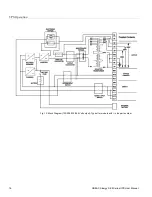
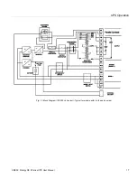
Fig. 11: Block Diagram (120/208/240 Volt output)– Typical for models with A in the part number
UPS Mode


