Installation
8
ONEAC Sinergy SE II Series UPS User Manual
Installation
WARNING: Before connecting any input wiring to the UPS, take precautions to insure that all circuits
being worked on are de-energized and proper lock-out/tag-out procedures have been followed. This is to
ensure that the live input source cannot accidentally be connected to the UPS during installation.
WARNING: Installation and operation should only be performed by qualified electrical personnel and
in conformity with local and national codes and applicable safety standards.
WARNING: Electrical shock hazard: Even when the UPS is disconnected from the mains, hazardous
voltages may still exist inside the UPS. The UPS receives power from more than one source—AC input
and DC input from batteries. All input sources (AC and DC) must, therefore, be disconnected before
carrying out installation or maintenance work inside the UPS.
NOTE: IEC/EN 62040-1 specifications do not include operation over 1000 meters. Contact Technical
Services for other applications.
ATTENTION: Some particularly sensitive electronic equipment may be susceptible to interference; in
order to prevent this it is suggested that input, output and any external battery cables to the UPS be housed
in properly grounded, metal conduits or that shielded cables be used. Routing of cables (e.g. power
supplies, communication or data lines) to other equipment should be kept separate from that of UPS cables.
External
Overcurrent
Protection and
Isolation Devices
External devices for the protection of wiring and for isolating the UPS should be installed upstream of the
equipment. Select and configure the isolating device by referring to Table 3, “Fuses or Circuit Breakers,”
on page 8. These devices must be designed to work with inductive loads such as transformers. Devices
should be provided in building installations and other locations.
The following table indicates the recommended size of input protection devices (circuit breakers and
fuses) that should be installed for the protection of both wiring and equipment.
To avoid spurious operation using GFCI breakers, these breakers must:
• be rated at differential current NOT LESS THAN 100 mA.
• be a SELECTIVE type (delayed intervention).
Emergency Switch
Device (ESD)/
Remote Power Off
(RPO) Function
For reasons of safety, a device having the characteristics of an Emergency Off button must be installed
externally of the UPS. This UPS is equipped with separate terminals for connecting hardwired customer
protection ESD relays.
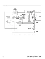
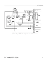
These external terminals, labeled “RPO,” are located next to the 9 pin SUB-D (interface COM3)
connector on the upper back section of the unit, see Figure 9.
If the circuit between the two RPO connector pins is “opened,” the output of the UPS is immediately
switched off.
The RPO circuit may be extended by connecting normally closed switches in series between the RPO
connection pins. Activating (opening) any of the series switches will causes the UPS to shut off its output.
Table 2. Installation Data
Ambient temperature
32°F to 104°F (0 °C to 40C°)
Relative humidity (non condensing)
90%
Environment
Controlled (i.e. Office or equivalent)
Max. altitude
3280 ft. above sea level (1000 m.a.s.l.)
Cable inlet
Rear Center
Air inlet
Front and Sides
Air outlet
Rear
Table 3. Fuses or Circuit Breakers
Description
4 & 6 kVA
8 & 10 kVA
Input: Fusible Disconnect/Breaker
40 Amps
70 Amps


