


INST.No.INE-471-P1CE Software Version 1.00
-7-
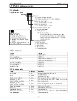
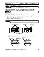
4.1 Laying cables
For laying cables, be careful of the following points.
(1) Separate cables from induction heating
oscillators or power lines.
(2) Keep cables not to get water- or oil-stained.
(3) Don’t bend cables extremely or apply any
excessive force to them.
(4) For a permanent layout, protect cables with
conduits, etc.
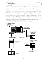
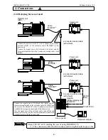
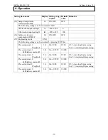
4.2 Single-detector-unit connection
The internal terminal board is accessible by removing the terminal board cover of the detector unit.
Lead in cables through the upper cable glands, and connect them to respective terminals.
Lead in the exclusive cable IR-WERP (
φ
10mm outer diameter) through the cable gland 1.
Lead in a signal cable through the cable grand 2.
Warning
Make sure to use the signal cable with the outer diameter of
φ
7.0 to 12.5mm.
For avoiding the risk of electric shock, make sure to turn off the power source to
this detector unit before wiring to the power terminals.
Use cables suiting to the applicable outer diameter of the cable gland; otherwise
waterproofing of the detector unit may deteriorate. Tighten the cable glands with
the nuts and fix the terminal board cover securely after wiring.
Reference
Caution
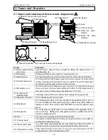
P+ P- OUT+ OUT- SA SB SG DI COM DOCOM IN+ IN-
24VDC 4-20mADC
RS-485
DIGITALIN DIGITALOUT 4-20mADC
P+ P- OUT+OUT- SA SB SG DI COM DO COM IN+ IN-
24VDC 4-20mADC
RS-485
DIGITALIN DIGITALOUT 4-20mADC
-V
+V
OUTPUT
DC 24V 2.1A
DC ON
DC LOW
V.ADJ
INPUT 50/60Hz
AC100- 240V 1.3A
Operator
interface/display unit,
personal computer or
sequencer
communication
output
Recorder, etc
.
Analog output: 4-20mA DC
Cable glands
• Outer diameter of applicable
cables
(ø7.0 to ø12.5mm)
Cable
(IR-WERP
)
Communication output :RS-485
Power unit
(IR-WEP)
P-
(Blue)
Power supply
100-120V AC
200-240V AC
Protective grounding
Contact input
Contact output
Correction input
P+
(Red)
G
(Green)
G (Gr
een
)
P+
(
Red
)
P- (Blue)
S
A
(Black
)
SB (White)
SG (Bro
wn
)
!
4. Connections
For conformance to CE
(1) Change 2 pieces of the resin
cable glands (standard) to the
supplied metal cable glands.
(2) Attach the supplied ferrite
cores to cables. You are
required to attach one ferrite
core to one cable at a place as
close to the cable gland.
Caution


