background image


16 

LT8227 (ISS 1) 

SECTION SIX Appliance Data (installation instructions) 


Wall Cut-out dimensions: 


Height   

555mm  

Width   

405mm 

Overall dimensions: 


Height   

599mm  

Width   

490mm 

Forward Projection: 


90mm, (From fireplace opening Including typical fret.) 

Weight:  


38.5kg (Boxed excluding fret) 

37kg (Unboxed excluding fret) 

Flue Length and duct length: 


100mm (minimum) to 600mm (maximum) 

Standard length supplied with fire is 600mm which can be cut down to the required length. 

No additional lengths or extensions can be used. 

Injector 

…………………………………………………………………………

MK 360  

Pressure Test Point Location: 


Gas inlet elbow 

Gas Connection: 


8.0mm O/D, tube. 

Data Badge Location:   


On the appliance base behind decorative front. 

Handset Replacement Batteries 2 x AAA 1.5V 

Power Supply Type Plug 

 Input: 100-240 VAC 50/60 Hz, 0.2A 


MODEL 

NG(G20)  

Category of appliance 

CII 

NO

X

 Class 

Efficiency Class 

Gas Category 

I2H 

Gas Type 

G20 Natural Gas 

Gas Pr/- 1.0mbar 

20 mbar 

Gas Input                          (Max) 

4.9 kW Gross  

                                          (Min) 

3.5 kW Gross 

Injectors size 

360 


NOTE: The efficiency of this appliance has been measured as specified in BS EN613-2001 and the result is 79.9% natural 
gas The gross calorific value of the fuel has been used for this efficiency calculation. GasTec have certified the test data 

from which it has been calculated. The efficiency value may be used in the UK Government’s Standard Assessment 

Procedure (SAP) for energy rating of dwellings. 

Summary of Contents for A-0804

Page 1: ...vicelogandfuturereference For use in Great Britain and Ireland Literature No 8227 ISS 1 IMPORTANT This appliance is guaranteed for 12 months subject to conditions The 5 year extended parts warranty will only be valid if the annual service recommended in this manual has been completed and appliance has been registered online ...

Page 2: ...T 30 SERVICE RECORD 31 EXTENDED FIVE YEAR PARTS WARRANTY In order to validate your extended 5 years parts warranty please read the Benchmark Scheme on the opposite page and ensure your installer has filled in the appropriate checklist This in no way reduces your statutory rights Your warranty commences from the date of purchase and you must retain your receipt or invoice as proof of a purchase dat...

Page 3: ...lations England and Wales All installations must be notified to Local Area Building Control either directly or through a Competent Persons Scheme A Building Regulations Compliance Certificate will then be issued to the customer who should on receipt write the Notification Number on the Benchmark Checklist This product should be serviced regularly to optimise its safety efficiency and performance T...

Page 4: ... the following details here and keep the receipt as proof of purchase This information maybe asked for when you contact the helpdesk MODEL Paragon Core BF Remote Control Serial No This information can be found on the label attached to the packaging and on the data badge which is located on the base of the appliance behind the control cover Retailer Name Address Date Of Purchase ...

Page 5: ...wrapped in polythene and be clearly labelled RCF waste These materials are not classified as hazardous waste and should be disposed of at a site licensed for the disposal of industrial waste The PARAGON CORE BF is an inset room sealed decorative fuel effect gas appliance The PARAGON CORE BF is available in Natural Gas G20 20 mbar Only The marking G20 for natural gas on the packaging and the data b...

Page 6: ...y above first Run the fire on high over a few days The first time you light your new appliance a smell may occur due to its new condition This is quite normal and will soon disappear after a few hours use at maximum setting open a window until the smell disappears The appliance MUST NOT be used if the glass panel is not correctly fitted or if this panel is cracked or broken Any debris should be cl...

Page 7: ...e the gas to be switched off if the flames are extinguished for any reason THIS DEVICE MUST NOT BE OVERRIDDEN If this situation occurs on a regular basis have the appliance checked by a qualified engineer The problem may be due to a blocked or restricted flue Before removing the fret trim glass or fuel bed for cleaning the fire should be turned off and left to cool down NOTE In use some discolorat...

Page 8: ...imately 20 25sec If the ignitor stops sparking and the pilot fails to light repeat this procedure B The appliance can be adjusted up or down by pressing the appropriate button low setting or high setting There are 5 heat settings and the fire will give a double bleep when the maximum or minimum heat setting is reached To switch off the appliance press the OFF button or if the appliance is to be sw...

Page 9: ...ith a soft clean dry cloth only The trim should be removed for cleaning The fret should be removed before removing the trim which is held in place by four magnets CLEANING BLACK PAINTED SURFACES These surfaces should be dusted regularly and any marks removed with a soft cloth Abrasive or chemical cleaner should never be used CLEANING GLASS PANEL From time to time it may be necessary to clean the g...

Page 10: ...in glass staining that cannot be removed by cleaning Re assemble in reverse order ensuring the seal is compressed evenly at the top and bottom Re fit the top canopy before re fitting the trim and fret or fascia and before re lighting CLEANING AND REPLACING Fuel Bed Parts Important Refer to the Health Safety Notice located on page 3 of this booklet before cleaning or replacing any refractory materi...

Page 11: ... to low for 15 minutes before turning off This will not eliminate all soot but helps keep it to a minimum LOG BED LAYOUT The Log set as shown consists of 1 Bag of vermiculite 3 Base shapes 10 Overlay log shapes 1 Pouch of Embaglow Place the front sump in position as shown ...

Page 12: ...12 LT8227 ISS 1 Place shape No1 directly onto the studs as shown Place a VERY thin layer of vermiculite over the burner as shown ...

Page 13: ...djenrick co uk 13 LT8227 ISS 1 Place Logs No2 No3 on top of the studs in the positions shown Loosely tease out the Embaglow into a fine nest and placein the areas as shown Take great care not to get any on the pilot ...

Page 14: ...14 LT8227 ISS 1 Fit the front three logs as shown Position log 7 on its location peg and log 8 within the channel on the base shape as shown 6 4 5 ...

Page 15: ...idges the gap Place log 10 on its location peg as shown Place the three remaining shapes as shown SECTION FIVE Replacement Parts user instructions The only user removable parts are Cast fret Top Canopy Glass panel fixing clamps and fret cover Decorative Trim Refractory fuel bed components ...

Page 16: ... O D tube Data Badge Location On the appliance base behind decorative front Handset Replacement Batteries 2 x AAA 1 5V Power Supply Type Plug Input 100 240 VAC 50 60 Hz 0 2A MODEL NG G20 Category of appliance CII NOX Class 5 Efficiency Class 1 Gas Category I2H Gas Type G20 Natural Gas Gas Pressure 1 0mbar 20 mbar Gas Input Max 4 9 kW Gross Min 3 5 kW Gross Injectors size 360 NOTE The efficiency of...

Page 17: ...ND BRITISH STANDARDS B S 5871 PART 2 B S 5440 PART 1 B S 6891 B S 1945 Note This appliance must be installed to current versions of the above standards and include any relevant amendments THE BUILDING REGULATIONS ISSUED BY THE DEPARTMENT OF THE ENVIRONMENT THE BUILDING STANDARDS SCOTLAND CONSOLIDATED REGULATIONS ISSUED BY THE SCOTTISH DEVELOPMENT OFFICE PRIOR TO THE INSTALLATION ENSURE THAT THE LO...

Page 18: ...ing the appliance all combustible materials must be removed from the rear faces as described in Section 10 GENERAL REQUIREMENTS The flue and air duct length must be between 100mm to 600mm The fire is supplied with a standard pipe length of 600mm The flue and air duct must not accommodate any bends The flue outlet must terminate on a suitable outside wall The minimum flue terminal clearances which ...

Page 19: ... minimum clearance from the hearth base of appliance to the underside of a combustible shelf should be determined using the shelf chart Minimum width between vertical sides of combustible surround should not be less than 800 mm provided fire is central to the surround and sides do not project more than 150 mm When vertical side forward projection is increased by 12 5 mm add 50 mm to inside width o...

Page 20: ...ower cable link to the transformer must be accessible for re pairing handset The cable can be routed using the following two methods Method 1 Passing the cable through the side of the chimney breast It is good practice to run the cable within a sleeve of at least 15mm internal diameter sealing the sleeve using a suitable sealant at the point the sleeve cable terminates the chimney masonry Method 2...

Page 21: ...ly through the wall ensure the hole is drilled accurately at the centre and square to the wall both horizontally and vertically Cut out the brickwork of the inner skin of the cavity wall for the lintel and position and fix the lintel with mortar Cut out the brickwork under the lintel between the two outside vertical lines into the cavity Ensure the cut out width is square try the appliance into th...

Page 22: ... dwelling reference must be made to the specific installation requirements stated later in this Section Installing The Appliance In Timber Framed Dwelling Ensure it is a suitable outside wall constructed of non combustible materials and that the flue position meets the requirements previously described Mark a horizontal line on the wall at the intended hearth surface or appliance base height 150mm...

Page 23: ...using plug and screws Pass the flue terminal through the core drilled hole and check the flue fully engages on the flue spigots Mark the fixing holes remove the terminal and drill the wall to accommodate the wall plugs Run two beads of flue seal or fire cement around the inside of both pipes to ensure airtight seal Fit the terminal to the wall and fix back with the screws provided If the flue outl...

Page 24: ...r should be cut around the pipe allowing a minimum 50mm air gap all around the pipe A non combustible sleeve 250mm diameter must be fitted to this clearance hole To ensure that any condensation formed on the duct pipes does not drip on to the inner wall a length of galvanised wire must wrapped around each flue pipe and secured in position by twisting the ends together Ensure that the twisted ends ...

Page 25: ...de from the front of the appliance from either the left or the right in 8mm dia pipe or a concealed connection from the rear of the appliance a hole with a grommet is provided at the rear An isolating cock is fitted in the supply feed to the fire to facilitate servicing It may be rotated for right gas connection When a concealed gas fitting from the rear is required it is necessary to route the pi...

Page 26: ...nd you must repeat the ignition procedure Check that the electrode is sparking at the gap between the thermocouple tip and the electrode and that the pilot ignition is established After approximately 20 seconds the main burner will light on the high setting Check that the inlet pressure 20mbar 1 mbar for natural gas or 37mbar 1 mbar for L P G Refit pressure test point screw and check for leaks SEC...

Page 27: ... damage the pilot head Replacement of Gas Control 1 Turn off the gas supply by the Restrictor Elbow and disconnect 2 Remove the stove front panel 3 Remove Glass See Section Four 4 Remove all loose fuel bed components 5 Disconnect battery leads and remove appliance battery pack Detach remote control eye from hearth See Section Seven when repositioning 6 Remove the fixing nut securing the valve carr...

Page 28: ... in reverse order turn on the gas supply check for soundness and re commission REPLACEMENT OF CONTROL UNIT EDB 1 Pull off the cable connections from the E D B board 2 Unscrew the retaining nut securing the E D B 3 Replace in reverse order 4 Reconnect the battery pack and test the operation of the appliance Replacement Handset Follow the guide stipulated on page 9 of the users instructions Changing...

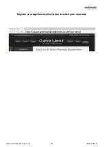
Page 29: ...www charltonandjenrick co uk 29 LT8227 ISS 1 Register your appliance online today to active your warranty ...

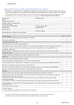
Page 30: ...coals logs pebbles etc been fitted to manufacturer s instructions Gas Supply Has an isolation valve inlet elbow been fitted for servicing Has the gas supply been thoroughly purged prior to connection to remove any debris Has a gas tightness test been completed prior to breaking into the gas supply and following completion of installation IGEM UP 1B Has the correct gas type been chosen as per manuf...

Page 31: ...ays use the manufacturer s specified spare part when replacing controls SERVICE 01 Date Engineer name Company name Telephone No Gas safe register No Comments Signature SERVICE 02 Date Engineer name Company name Telephone No Gas safe register No Comments Signature SERVICE 03 Date Engineer name Company name Telephone No Gas safe register No Comments Signature SERVICE 04 Date Engineer name Company na...

Page 32: ...sembly AAA Batteries x 2 Embaglo Fixing Kit A 0474 Grommet 4554 Silicone seal 4818 Connection Pipe 7mm Nut Spinner Spare Fixings Bagged A 0411 Air Test Completed Hand Remote Bluetooth Warning Label Fire Guard Magnets 4 x 3048 9v Transformer Glass Assembly Canopy 4540 Fret Plate Owners Book Serial Number Inspector ...

Reviews: