14
Part 6:
REPLACEMENT PARTS
CONTR
OL
TRANSFORMER
MAIN TERMINAL BO
ARD
26
27
35
37
RINSE
W
ASH
DRIVE
MRA
19
20
CB
24
25
GR
OUND
28
36
MO
T
OR CONT
A
CT
ORS
RINSE
W
ASH
DRIVE
21
MRA
FU1
FU2
22
23
33
34
18
TIMERS
RT
WT
32
31
CONTR
OL RELA
YS
120V
120V
120V
120V
120V
120V
120V
120V
29
30
29
30
OFF
ST
AR
T
FINAL RINSE
W
A
TER PRIME
LO
W RINSE
TEMP ALARM
ST
OP
ON
PO
WER ON
1
2
3
11
12
38
13
15
16
17
14
3
4
5
6
6
12
13
6
7
8
9
10
9
10
3
39
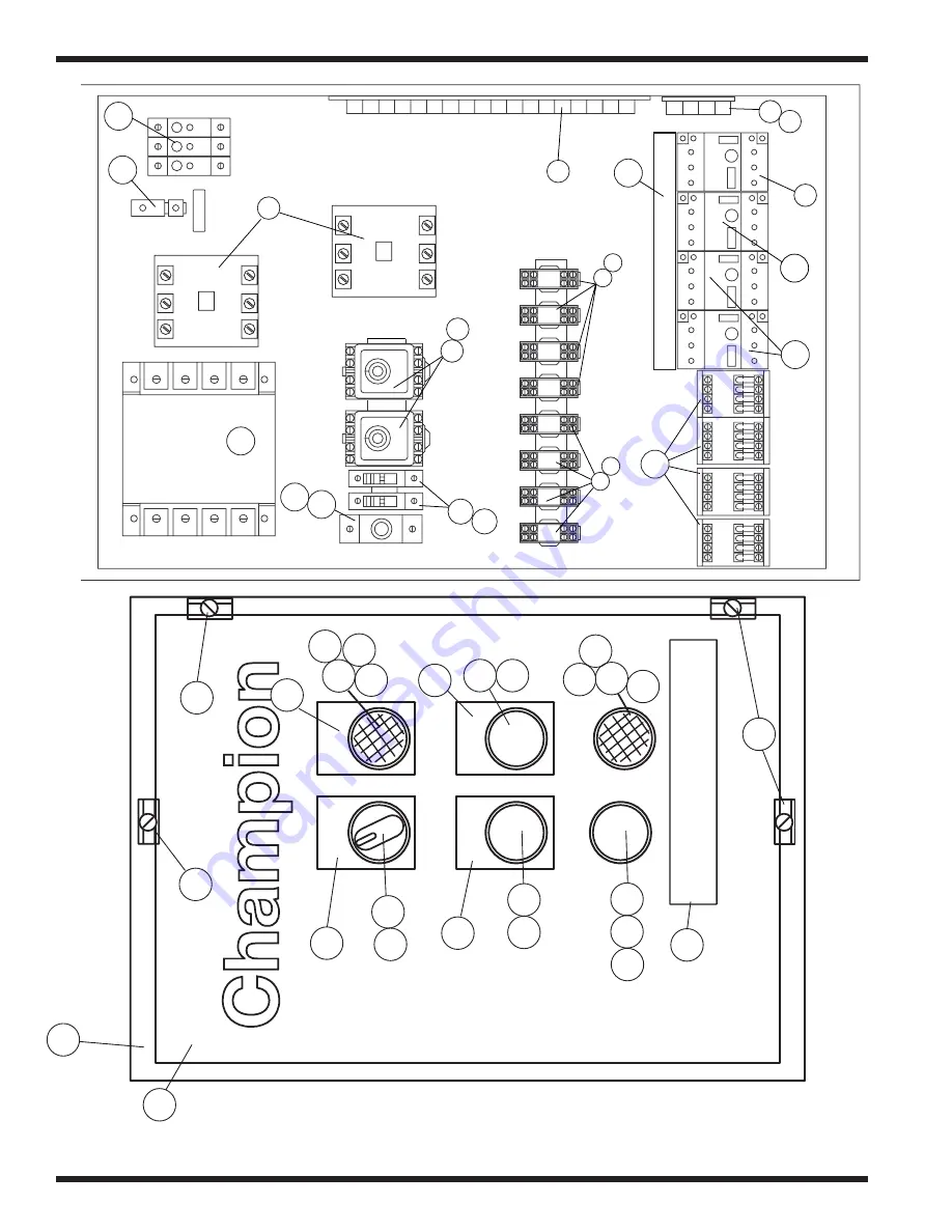
Figure 6.17b-
Steam or Electric Remote Control Cabinet
(For machines beginning with S/N J1080 and above)
92b
Summary of Contents for 135-USN-72
Page 1: ......
Page 3: ...TECHNICAL PUBLICATION SHEET i TECHNICAL PUBLICATION SHEET ...
Page 4: ...TECHNICAL MANUAL VALIDATION CERTIFICATE ii TECHNICAL MANUAL VALIDATION CERTIFICATE ...
Page 5: ...APPROVAL AND PROCUREMENT RECORD iii APPROVAL AND PROCUREMENT RECORD ...
Page 9: ...vii THIS PAGE INTENTIONALLY LEFT BLANK ...
Page 36: ...THIS PAGE INTENTIONALLY LEFT BLANK 18 ...
Page 74: ...56 Part 6 REPLACEMENT PARTS THIS PAGE INTENTIONALLY LEFT BLANK ...
Page 83: ...65 Part 6 REPLACEMENT PARTS THIS PAGE INTENTIONALLY LEFT BLANK ...
Page 96: ...74 Part 6 REPLACEMENT PARTS Figure 6 8 Rinse saver assembly 1 2 3 4 9 10 11 2 2 12 5 4 6 7 8 ...
Page 98: ...76 Part 6 REPLACEMENT PARTS Figure 6 9 Steam coil assembly Tank 4 8 9 10 7 6 5 4 1 2 3 ...
Page 126: ...94 Part 6 REPLACEMENT PARTS Figure 6 18 Dishracks and PRV 1 2 3 ...
Page 130: ...98 Part 6 REPLACEMENT PARTS 1 2 3 4 5 6 7 8 9 Figure 6 20 MRAN 90 Pawl Bar ...
Page 142: ...110 Part 6 REPLACEMENT P ARTS THIS PAGE INTENTIONALLY LEFT BLANK ...
Page 143: ...111 Part 6 REPLACEMENT P ARTS PART 7 ELECTRICAL SCHEMATICS Part 7 ELECTRICAL SCHEMA TICS ...
Page 159: ...112 THIS PAGE INTENTIONALLY LEFT BLANK ...
Page 160: ...112 THIS PAGE INTENTIONALLY LEFT BLANK ...
Page 163: ...115 Part 6 REPLACEMENT P ARTS ...