9.0 Parts List & Sequence of Operations
78
9.16 Electrical Sequence of Operation
NOTE: Please see the section on Hydraulic Sequence of Operation for more details.
Electrical Sequence of Operation
Electrical Schematic References
Schematic Drawing Number: E-2853
A. Turn Main Disconnect switch to “on” position.
If fuses F7 and F4 are conductive, power is brought to
the main control board (EE-2807-1). The line lights will
illuminate. Power is also brought to the circuit board.
Fuse F1 and F3 are located on the main control board
in the power panel. If fuse F3 is conductive, power will
be supplied to the logic on the board. If the logic is
functioning, the operator’s console display will function.
If fuse F1 and FL are conductive, power will be
supplied for backgauge movement.
B. Press CLEAR key on the keyboard to direct
the backgauge forward through the presetter.
To coordinate the console display with the actual
backgauge position, the backgauge must be brought
forward through the presetter. When the backgauge
position reaches approximately five inches, the
presetter, located beneath the table, is actuated. The
display will then count up and down from this point as
signals are received from the incremental encoder. For
general backgauge information see C below.
C. Backgauge control via keyboard.
The backgauge glide control on the keyboard is used
to manually control the backgauge position. The speed
of the backgauge motor will depend upon where the
actuator is pressed. The backgauge glide control acts
as a potentiometer, which controls the voltage that is
sent to the backgauge motor. If the backgauge motor
fails to move, the following should be checked: The
CLAMP UP prox. (IN 2), the HYD UP prox (IN 3), and
the KNIFE UP prox (IN 4) should be off.
D. Make a cut by closing the guard and pressing
the cut button.
When the front guard is close, contacts for the left (A)
and right (B) safety interlocks close. The CUT button
LIGHT will light up, indicating that the machine is ready
to cut. When the CUT button is pressed, the hydraulic
motor relay (PUMP RELAY) will energize, and power
will be brought to the hydraulic motor. The KNIFE
LATCH solenoid will energize and the knife latch will
pull in. CUT solenoid A, B, and unload valve will
energize, and the machine will make a cut. When the
knife reaches the down position, the KNIFE DOWN
prox (IN 9) will open, which after a slight time delay,
causes the logic to de-energize the CUT solenoids,
bringing the knife and clamp to the up position. When
the clamp reaches the up position, the HYD UP prox.
(IN 3) will close, which causes the logic to de-energize
the unload valve. The hydraulic motor will stop after a
preset idle time.
Summary of Contents for Titan 265
Page 60: ...9 0 Parts List Sequence of Operations 59 9 2 Main Assembly Side View 44000 Sht 2 Rev J...
Page 61: ...9 0 Parts List Sequence of Operations 60 9 3 Main Assembly Rear View 44000 Sht 3 Rev E...
Page 62: ...9 0 Parts List Sequence of Operations 61 9 4 Main Assembly Table View 44000 Sht 4 Rev E...
Page 63: ...9 0 Parts List Sequence of Operations 62 9 5 Main Assembly Parts List 44000 Sht 5 Rev S...
Page 64: ...9 0 Parts List Sequence of Operations 63 Main Assembly Parts List continued 44000 Sht 6 Rev N...
Page 65: ...9 0 Parts List Sequence of Operations 64 9 6 Main Assembly Cut Buttons 44000 Sht 7 Rev H...
Page 66: ...9 0 Parts List Sequence of Operations 65 9 7 Main Assembly Front Shield 44000 Sht 7 Rev H...
Page 67: ...9 0 Parts List Sequence of Operations 66 9 8 Electrical Panel Assembly EE 2879 Rev H...
Page 68: ...9 0 Parts List Sequence of Operations 67 Electrical Panel Assembly continued EE 2879 Rev H...
Page 69: ...9 0 Parts List Sequence of Operations 68 Electrical Panel Assembly continued EE 2879 Rev H...
Page 71: ...9 0 Parts List Sequence of Operations 70 9 10 Hydraulic Power Unit Assembly H 507 Rev E...
Page 72: ...9 0 Parts List Sequence of Operations 71 Hydraulic Power Unit Assembly continued H 507 Rev E...
Page 73: ...9 0 Parts List Sequence of Operations 72 9 11 Manifold Assembly H 516 Sheet 1 Rev C...
Page 74: ...9 0 Parts List Sequence of Operations 73 9 12 Hydraulic Schematic H 516 Sheet 2 Rev B...
Page 75: ...9 0 Parts List Sequence of Operations 74 9 13 Manifold Sub Plate Assembly H 517...
Page 76: ...9 0 Parts List Sequence of Operations 75 9 14 Sequence Check Valve Assembly H 551 Rev A...
Page 77: ...9 0 Parts List Sequence of Operations 76 9 15 Basic Machine Schematic E 2853 Rev C...
Page 78: ...9 0 Parts List Sequence of Operations 77 Basic Machine Schematic continued E 2853 Rev C...
Page 80: ...9 0 Parts List Sequence of Operations 79 9 17 Cut Button Assembly EE 2851 1...
Page 81: ...9 0 Parts List Sequence of Operations 80 9 18 Control Console Assembly EE 2773 1 Rev C...
Page 82: ...9 0 Parts List Sequence of Operations 81 9 19 Control P C Assembly EE 2807 1...
Page 83: ...9 0 Parts List Sequence of Operations 82 9 20 Power Panel Label S 1781 54 Rev C...
Page 85: ...9 0 Parts List Sequence of Operations 84 9 22 Knife Latch Assembly 47568 Rev C...
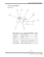
Page 86: ...9 0 Parts List Sequence of Operations 85 9 23 Line Light Assembly EE 2779 Rev B...


