8.0 Maintenance Guide
54
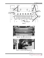
Figure 35
8.7.5 Hydraulic Adjustments
Note:
When adjusting valves, first loosen the jam nut around the stem, then use a hex allen wrench
to turn the stem clockwise to increase pressure, or counterclockwise to decrease pressure.
Pressure Settings:
1. Main System Relief Pressure — 2,000 psi.
2. Knife Down Sequence Pressure — 1,200 psi.
3. Clamp/Knife up Sequence Pressure — Visual.
4. Clamp Pressure Reducer — 400-900 psi.
Adjustment Procedure:
Note: On all valves, turning in (clockwise) increases pressure; out (counter-clockwise)
decreases pressure.
1. Remove the lower front cover panel.
2. MAIN SYSTEM RELIEF PRESSURE: Use the Knife Down command in Maintenance Mode
to send the knife and clamp down. Read the pressure on the Main System gauge when the
knife is bottomed on the table. Adjust the main system relief valve (Figure 36, pg. 55) to
obtain a reading of 2,000 psi. It may be necessary to send the knife down several times.
Hose
Clamp
Mounting
Plate
Actuator
Plate
Summary of Contents for Titan 265
Page 60: ...9 0 Parts List Sequence of Operations 59 9 2 Main Assembly Side View 44000 Sht 2 Rev J...
Page 61: ...9 0 Parts List Sequence of Operations 60 9 3 Main Assembly Rear View 44000 Sht 3 Rev E...
Page 62: ...9 0 Parts List Sequence of Operations 61 9 4 Main Assembly Table View 44000 Sht 4 Rev E...
Page 63: ...9 0 Parts List Sequence of Operations 62 9 5 Main Assembly Parts List 44000 Sht 5 Rev S...
Page 64: ...9 0 Parts List Sequence of Operations 63 Main Assembly Parts List continued 44000 Sht 6 Rev N...
Page 65: ...9 0 Parts List Sequence of Operations 64 9 6 Main Assembly Cut Buttons 44000 Sht 7 Rev H...
Page 66: ...9 0 Parts List Sequence of Operations 65 9 7 Main Assembly Front Shield 44000 Sht 7 Rev H...
Page 67: ...9 0 Parts List Sequence of Operations 66 9 8 Electrical Panel Assembly EE 2879 Rev H...
Page 68: ...9 0 Parts List Sequence of Operations 67 Electrical Panel Assembly continued EE 2879 Rev H...
Page 69: ...9 0 Parts List Sequence of Operations 68 Electrical Panel Assembly continued EE 2879 Rev H...
Page 71: ...9 0 Parts List Sequence of Operations 70 9 10 Hydraulic Power Unit Assembly H 507 Rev E...
Page 72: ...9 0 Parts List Sequence of Operations 71 Hydraulic Power Unit Assembly continued H 507 Rev E...
Page 73: ...9 0 Parts List Sequence of Operations 72 9 11 Manifold Assembly H 516 Sheet 1 Rev C...
Page 74: ...9 0 Parts List Sequence of Operations 73 9 12 Hydraulic Schematic H 516 Sheet 2 Rev B...
Page 75: ...9 0 Parts List Sequence of Operations 74 9 13 Manifold Sub Plate Assembly H 517...
Page 76: ...9 0 Parts List Sequence of Operations 75 9 14 Sequence Check Valve Assembly H 551 Rev A...
Page 77: ...9 0 Parts List Sequence of Operations 76 9 15 Basic Machine Schematic E 2853 Rev C...
Page 78: ...9 0 Parts List Sequence of Operations 77 Basic Machine Schematic continued E 2853 Rev C...
Page 80: ...9 0 Parts List Sequence of Operations 79 9 17 Cut Button Assembly EE 2851 1...
Page 81: ...9 0 Parts List Sequence of Operations 80 9 18 Control Console Assembly EE 2773 1 Rev C...
Page 82: ...9 0 Parts List Sequence of Operations 81 9 19 Control P C Assembly EE 2807 1...
Page 83: ...9 0 Parts List Sequence of Operations 82 9 20 Power Panel Label S 1781 54 Rev C...
Page 85: ...9 0 Parts List Sequence of Operations 84 9 22 Knife Latch Assembly 47568 Rev C...
Page 86: ...9 0 Parts List Sequence of Operations 85 9 23 Line Light Assembly EE 2779 Rev B...


