9-1
9 Crankshaft /Transmission
9
Contents
Exploded View
………………………………………………………………………………………………………9-3
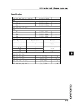
Specification
…………………………………………………………………………………………………………9-7
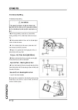
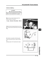
Crankcase Splitting
…………………………………………………………………………………………………9-10
Crankcase Splitting
………………………………………………………………………………………………9-10
Crankcase Assembly
……………………………………………………………………………………………9-12
Crankshaft and Connecting Rods
…………………………………………………………………………………9-18
Crankshaft Removal
……………………………………………………………………………………………9-18
Crankshaft Installation
…………………………………………………………………………………………9-18
Connecting Rod Removal
………………………………………………………………………………………9-19
Connecting Rod Installation
……………………………………………………………………………………9-19
Connecting Rod Bend
…………………………………………………………………………………………9-22
Connecting Rod Twist
……………………………………………………………………………………………9-22
Connecting Rod Big End Side Clearance
……………………………………………………………………9-22
Connecting Rod Big End Bearing Insert/ Crankpin Wear
………………………………………………… 9-23
Crankshaft Side Clearance
……………………………………………………………………………………9-24
Crankshaft Runout
………………………………………………………………………………………………9-25
Crankshaft Main Bearing Insert/Journal Wear
………………………………………………………………9-25
Balancer
……………………………………………………………………………………………………………9-27
Balancer Removal
…………………………………………………………………………………………………9-27
Balancer Installation
……………………………………………………………………………………………9-27
Insert/Journal Clearance
………………………………………………………………………………………9-27
Transmission
………………………………………………………………………………………………………9-29
Shift Pedal Removal
……………………………………………………………………………………………9-29
Shift Pedal Installation
…………………………………………………………………………………………9-29
Shift Mechanism Removal
……………………………………………………………………………………9-29
Shift Mechanism Installation
…………………………………………………………………………………9-30
Shift Mechanism Inspection
……………………………………………………………………………………9-31
Transmission Assy Removal
…………………………………………………………………………………9-32
Transmission Assy Disassembly
……………………………………………………………………………9-33
Transmission Assy Assembly
…………………………………………………………………………………9-34
Transmission Assy Installatiion
………………………………………………………………………………9-35
Transmission Shaft Disassembly
………………………………………………………………………………9-36
Transmission Shaft Assembly
…………………………………………………………………………………9-36
Shift Fork Bending
………………………………………………………………………………………………9-39
Summary of Contents for CF400-A 2017
Page 1: ...WWW CFMOTO COM Service manual CF400 A CF650 7B ...
Page 2: ...All right reserved ZHEJIANG CFMOTO POWER CO LTD Sep 2017 WWW CFMOTO COM ...
Page 31: ...2 13 2 Periodic maintenance 2 Special tool ...
Page 74: ...3 2 CFMOTO Exploded View ...
Page 148: ...4 2 Exploded view ...
Page 153: ...4 Cooling system 4 4 7 Special tool Bearing pressor Oil seal pressor ...
Page 168: ...5 3 5 Engine top 5 Exploded view ...
Page 170: ...5 5 5 Engine top 5 Exploded view ...
Page 174: ...5 9 5 Engine top 5 Special tool and sealant ...
Page 203: ...6 2 CFMOTO Exploded view ...
Page 206: ...6 Clutch 6 5 6 Clutch holder Sealant Special tool and sealant ...
Page 220: ...7 2 CFMOTO Exploded view ...
Page 222: ...7 4 CFMOTO Engine Oil Flow Chart ...
Page 223: ...7 Engine Lubrication system 7 5 7 Engine Oil Flow Chart ...
Page 237: ...8 2 CFMOTO Exploded view ...
Page 245: ...9 3 9 Crankshaft Transmission 9 Exploded view ...
Page 247: ...9 5 9 Crankshaft Transmission 9 Exploded view ...
Page 284: ...10 2 CFMOTO Exploded view ...
Page 300: ...11 2 CFMOTO Exploded view ...
Page 314: ...12 Breakingsystem 12 3 12 Exploded view Front break ...
Page 316: ...12 Breakingsystem 12 5 12 Exploded view Rear break ...
Page 319: ...12 8 CFMOTO Special tool Retainer plier Hand tester Jack Jack accessories ...
Page 335: ...13 2 CFMOTO Frontfork exploded view ...
Page 337: ...13 4 CFMOTO Rearswing armexplodedview ...
Page 350: ...14 2 CFMOTO Exploded view ...
Page 372: ...16 4 CFMOTO Parts location 1 2 3 4 5 6 7 8 9 10 11 12 13 14 15 16 17 18 19 20 22 21 ...
Page 402: ...Ignition System Ignition system wiring diagram 16 34 CFMOTO ...
Page 409: ...16 Electrical system 16 41 16 Starting system Starting system wiring ...


