


3-30
CFMOTO
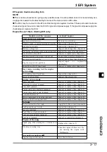
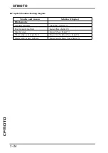
Self diagnose
EFI trouble back up
ECU has the back up solution below to protect the engine when EFI part got trouble.
Trouble
code
Parts
Signal not stable or out
of standard
ECU settings
P0112 or
P0113
Intake
temp
sensor
Intake temp.
Ta=
-
40°C~+130°C
If intake temp sensor trouble or
disconnected
,
ECU temp is -40°C
;
If intake temp sensor trouble or short
circuit
,
ECU temp is 130°C
;
P0117 or
P0118
Water
temp
sensor
Water temp
Tw=
-
40°C~+129°C
If water temp sensor trouble or
disconnected
,
ECU temp is -40°C
;
If water temp sensor trouble or short
circuit ECU temp is 129°C
P0130
、
P0131
、
P0132
and
P0134
Oxygen
sensor #1
T he oxygen sensor is
active and sensor must
send signals (output
voltage) continuously to
the ECU.
If the oxygen sensor is not activated, the
ECU stops oxygen sensor feedback
mode.
P0136
、
P0137
、
P0138
and
P0140
Oxygen
sensor #2
T he oxygen sensor is
active and sensor must
send signals (output
voltage) continuously to
the ECU.
If the oxygen sensor is not activated, the
ECU stops oxygen sensor feedback
mode.
Summary of Contents for CF400-A 2017
Page 1: ...WWW CFMOTO COM Service manual CF400 A CF650 7B ...
Page 2: ...All right reserved ZHEJIANG CFMOTO POWER CO LTD Sep 2017 WWW CFMOTO COM ...
Page 31: ...2 13 2 Periodic maintenance 2 Special tool ...
Page 74: ...3 2 CFMOTO Exploded View ...
Page 148: ...4 2 Exploded view ...
Page 153: ...4 Cooling system 4 4 7 Special tool Bearing pressor Oil seal pressor ...
Page 168: ...5 3 5 Engine top 5 Exploded view ...
Page 170: ...5 5 5 Engine top 5 Exploded view ...
Page 174: ...5 9 5 Engine top 5 Special tool and sealant ...
Page 203: ...6 2 CFMOTO Exploded view ...
Page 206: ...6 Clutch 6 5 6 Clutch holder Sealant Special tool and sealant ...
Page 220: ...7 2 CFMOTO Exploded view ...
Page 222: ...7 4 CFMOTO Engine Oil Flow Chart ...
Page 223: ...7 Engine Lubrication system 7 5 7 Engine Oil Flow Chart ...
Page 237: ...8 2 CFMOTO Exploded view ...
Page 245: ...9 3 9 Crankshaft Transmission 9 Exploded view ...
Page 247: ...9 5 9 Crankshaft Transmission 9 Exploded view ...
Page 284: ...10 2 CFMOTO Exploded view ...
Page 300: ...11 2 CFMOTO Exploded view ...
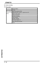
Page 314: ...12 Breakingsystem 12 3 12 Exploded view Front break ...
Page 316: ...12 Breakingsystem 12 5 12 Exploded view Rear break ...
Page 319: ...12 8 CFMOTO Special tool Retainer plier Hand tester Jack Jack accessories ...
Page 335: ...13 2 CFMOTO Frontfork exploded view ...
Page 337: ...13 4 CFMOTO Rearswing armexplodedview ...
Page 350: ...14 2 CFMOTO Exploded view ...
Page 372: ...16 4 CFMOTO Parts location 1 2 3 4 5 6 7 8 9 10 11 12 13 14 15 16 17 18 19 20 22 21 ...
Page 402: ...Ignition System Ignition system wiring diagram 16 34 CFMOTO ...
Page 409: ...16 Electrical system 16 41 16 Starting system Starting system wiring ...


