9
01-10-98
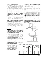
CLEARANCES
ALL HEATERS
For clearances from combustible surfaces, see the
chart below.
CLEARANCE FROM COMBUSTIBLE
MATERIAL (mm)
Plant Room Installation
Model
Top
Back
Right
Left
Front
055
900
50
150
150
Clear
105
900
50
150
150
Clear
155
1050
300
150
300
Clear
185-405
750
150
300
150
Clear
Outdoor Installation
Model
Top Back
Right
Left
Front
055
Clear
50
150
150
Clear
105
Clear
50
150
150
Clear
155
Clear
300
150
150
Clear
185-405
Clear
150
150
150
Clear
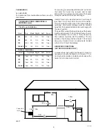
4'
Min
4'
Min
Forced Air
Inlet
4' Min
10'
Min.
1' Min
1.0m 3' Min
3.0m
1.25m
1.25m
1.25m
0.3m
For servicing, provide at least 600mm (24") in front of
the heater for burner tray removal, and at least
450mm (18") on water connection side of the heater
to inspect and delime the heat exchanger.
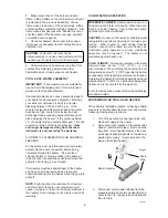
Heaters must not be installed under an overhang of
less than 1.0m (3 feet) from the top of the heater.
Three (3) sides must be open in the area under the
overhang. Roof water drainage must be diverted
away from the heaters installed under overhangs with
the use of gutters:
The point from where the flue products exit the heater
must be a minimum of 1.25m (4 feet ) below, four (4)
feet horizontally from or 0.3m (1 foot) above any
door, window or gravity inlet to a building. The top
surface of the heater shall be at least 1.0m (3 feet)
above any forced air inlet, or intake ducts located
within 3.0m (10 feet) horizontally.
HIGH WIND CONDITIONS
(OUTDOOR HEATERS ONLY)
In areas where high winds are frequent, it may be
necessary to locate the heater a minimum of 1.0 m
from high vertical walls, or install a wind break so the
heater is not in direct wind current.
clear.tif

