01-10-98
28
185, 265 & 405 Models
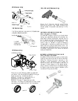
PILOT REMOVAL AND CLEANING
1.
Disconnect pilot tubing, and wires from
gas valve.
2.
Remove pilot assembly from burner tray.
3.
Remove pilot from bracket.
4.
Remove pilot injector and clean with
wire or small brush.
CAUTION!
Do
not
enlarge hole in pilot orifice.
5.
Reverse above procedure to re-install.
HEAT EXCHANGER REMOVAL
1.
Shut water, gas and electricity off, close
valves and relieve pressure, remove relief
valve. Remove side inspection panels.
2.
Remove top holding screws.
3.
Remove draft diverter, lift and remove top
and flue collector. Remove inspection
panels.
4.
Loosen bolts and disconnect flange nuts
on inlet-outlet header, loosen union(s) at
gas pipe and slide boiler away from piping
until studs clear the header.
5.
Lift heat exchanger straight up using
caution not to damage refractory.
6.
Reverse above procedure to reinstall.
055, 105 & 155 Models
HEAT EXCHANGER REMOVAL
1.
Shut water, gas, and electricity off, close
valves and relieve pressure.
2.
Drain heat exchanger.
3.
Loosen and remove flange bolts.
4.
Remove flange and inlet/outlet pipes from
the header.
5.
Remove outdoor stackless top or indoor
stack top from unit.
6.
Remove jacket top, flue collector, and
baffles.
7.
Remove upper front jacket panel, and
disconnect wires at toggle switch.
8.
Remove capillary bulb from inlet/outlet
header.
9.
Disconnect press switch tube from return
header.
10. Disconnect hi-limit wire from thermostat, and
pressure switch. Remove overheat
thermostat capilliary & phial.
11. Lift heat exchanger straight up from
combustion chamber, using caution not to
damage refractory.
12. Reverse above procedure to re-install.
All Models
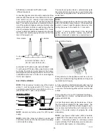
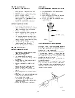
CONTROL IMMERSION WELL REPLACEMENT
1.
Shut water off to heater and drain heat
exchanger.
2.
Remove jacket top panel.
3.
Remove old control well with bushing and
sleeve, with 7/8" wrench or socket.
4.
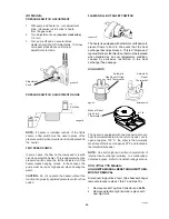
Slip "o" ring gasket over control well and
install in header.
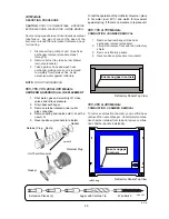
TUBE CLEANING PROCEDURE (Typical)
Establish a regular inspection schedule, frequency
depending on local water condition and severity of
service. Do not let the tubes clog up solidly. Clean out
deposits over 1.5 mm in thickness.
The heater must be cleaned from the rear as shown.
It is preferable, however, to remove the heat
exchanger and the in/out header for better visibility
through the tubes and to be sure the ground-up lime
dust does not get into the system,
Note that you do not remove the top panel or the heat
exchanger, generally.
After reaming, mount the wire brush in place of the
auger and clean out debris remaining in the tubes.
Another method is to remove the heat exchanger,
ream tubes and immerse heat exchanger in non-
inhibited de-scale solvent.
Well Assembly
Olive
well.tif
drill.tif

