15
2-06-04
GAS SUPPLY CONNECTIONS
Gas piping must have a manual shut-off valve located
outside the heater jacket. All gas piping should be
tested after installation in accordance with local
codes.
CAUTION:
The heater and its manual shut off valve
must be disconnected from the gas supply during any
pressure testing of that system at test pressures in
excess of 150mbar (2.2psi). Dissipate test pressure
in the gas supply line before reconnecting the heater
and its manual shut off valve to gas supply line.
FAILURE TO FOLLOW THIS PROCEDURE MAY
DAMAGE THE GAS VALVE. OVER PRESSURED
GAS VALVES ARE NOT COVERED BY WAR-
RANTY. The heater and its gas connections shall be
leak tested before placing the appliance in operation.
Use soapy water for leak test. DO NOT use open
flame.
NOTE:
Do not use PTFE tape on the gas line pipe
thread. A flexible sealant is recommended.
Models 055 and 105 are fittef with a ½" BSP gascock,
all others have a ¾" gascock.
A minimum of 20 mbar (8”) WG and a maximum of 22
mbar (8¾”) W.G.upstream pressure under load, and
no load conditions are provided for natural gas or a
minimum of 37mbar (14¾”) W.G.and a maximum of
45 mbar (18”) W.G for propane gas.
GAS PRESSURE
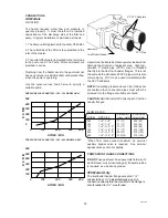
For LPG Heaters the gas pressure is regulated by
the injectors fitted in the factory. There is no
adjustment.
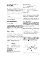
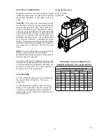
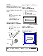
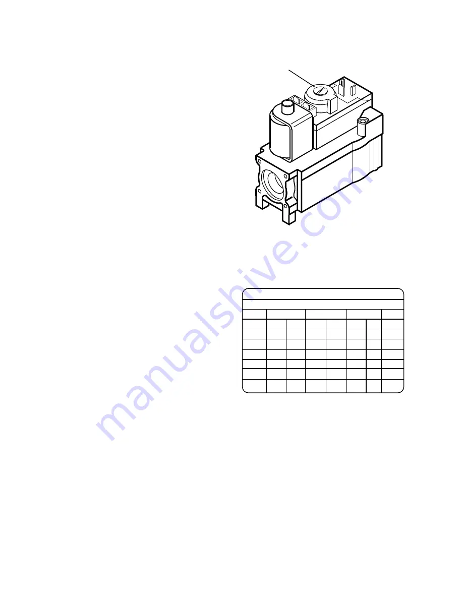
For NG Heaters the regulator on the gas valve is
factory set. If adjustment is required, remove the
cap and turn the adjustment screw clockwise to
increase and counter-clockwiese to decrease the
burner pressure.
Honeywell Gas Valve
Burner Pressure
adjustment
PIPE SIZING FOR GAS CONNECTIONS
MAXIMUM EQUIVALENT PIPE LENGTH METRES
N
- NATURAL GAS @ 1.0 mbar PRESSURE DROP
P
- L.P.G. @ 2.5 mbar
PRESSURE DROP
10mm
15mm
22mm
28mm
MODEL
N
P
N
P
N
P
N
055
6
12
15
105
3
5
20
155
10.5
>24
36
185
8
>24
29
265
4.5
18
14.5
405
8.5
7

