


6800040 01
RESERVOIR
CAP
1
6720050
02 OIL
RESERVOIR
1
6480055 03
MAIN HANDLE
1
6360250
★
04 O-RING
1
6740100
★
05
5/32" BALL 1
6520160
★
06
SUCTION SPRING 1
6740020
★
07 1/4" BALL
1
6520200
★
08 SPRING
1
6340590 09
BALL POSITIONING DOWEL
1
6360270
★
10
▲
O-RING
1
6040181
★
11
▲
BACK-UP RING
1
6160027
12
BODY
1
6860101 13 HEAD
1
6620171 14
▲
RAM
1
6361810
★
15
▲
SEAL
1
6641020
★
16
▲
M 6 COPPER WASHER
1
6900334
17
▲
M 6x30 SCREW
1
6420231 18 LOWER BLADE
1
6560691 19
UPPER BLADE PIN
1
6040421
20 Ø 10 CIRCLIP
1
6900315 21
●
M 6x16 SCREW
4
6370141 22
●
LOWER BLADE LEFT GUIDE 1
6420241 23
●
UPPER BLADE 1
6370151 24
●
LOWER BLADE RIGHT GUIDE 1
6700140
★
25
●
CIRCLIP
1
6560701 26
●
LATCH PIN
1
6520460 27
●
SPRING
1
6200051 28
●
LATCH 1
6370250
29 BLADE HOLDING SCREW 1
6080051 30
▲
RAM BUSHING
1
6522314 31
▲
BLADE RETURN SPRING
1
6360266
★
32
O-RING
1
6360161
★
33
O-RING
1
6560262 34
MOVABLE HANDLE PIN
2
6700060
★
35
CIRCLIP
4
6040101
★
36 BACK-UP RING
1
6362020
★
37
SEAL
1
6620090 38
PUMPING
RAM
1
6360240
★
39
O-RING
1
6340590 40
BALL POSITIONING DOWEL
1
6520200
★
41 SPRING
1
6740020
★
42 1/4" BALL
1
6232000 43
LABEL (TG. 0351)
1
6480197 44
MOVEABLE HANDLE 1
6380200 45
HANDLE GRIP 1
6895020 46
MAX PRESSURE VALVE
1
6040080
★
47
BACK-UP RING 1
6360140
★
48 O-RING
1
6020027 49
PRESSURE RELEASE PIN
1
6600020
50
SPRING LOADED PIN
1
6520280
★
51 SPRING
1
6360120
★
52
O-RING
1
6740120
★
53 7/32"
BALL
1
6600100 54 BALL SUPPORT
1
6520520
★
55 SPRING
1
6360166
★
56 O-RING
1
6900341
57
M 8x10 SCREW
1
6440100 58
PRESSURE RELEASE LEVER 1
6760100
59
ø 3x16 SPLIT PIN 1
6232303 60
METAL LABEL (TG. 0503) 1
6650118
61
RIVET ø 2,5 x 3,5
2
6635011 62
PRESSURE RELEASE PIN
1
6520861 63 SPRING
1
6340720 64
PRESSURE RELEASE DOWEL 1
6520160
★
65
SUCTION SPRING 1
6740100
★
66
5/32" BALL 1
6641020
★
67
M 6 COPPER WASHER 1
6900601 66
SUCTION SCREW
1
6860131
●
HEAD ASSEMBLY
6780271
▲
COMPLETE RAM
6000088
★
SPARE PARTS PACKAGE
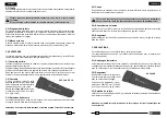
5. CAMBIO DELLE LAME
(Rif. a Fig. 3)
Può accadere che, per un uso prolungato o improprio, le lame perdano il fi lo oppure si
danneggino. La sostituzione delle lame vecchie con le nuove é semplice:
5.1) Lama inferiore
– Sganciare il dente di arresto (28) e far ruotare il complesso superiore aprendolo comple-
tamente fi no alla battuta.
– Azionare il manico mobile facendo avanzare la lama inferiore (18) fi no a mettere in
vista il grano di fi ssaggio (29) sul pistone (14).
– Con un cacciavite svitare il grano (29) liberando così la lama (18).
– Togliere la vecchia lama dall'apposita sede del pistone, inserirvi la nuova e bloccarla
con lo stesso grano.
Attenzione: prima di richiudere il complesso superiore, rilasciare la pressione del-
l'olio facendo arretrare completamente la lama (18); in caso contrario il complesso
superiore potrebbe urtare contro lo spigolo della lama inferiore danneggiandola.
5.2) Lama superiore
– Aprire la testa sganciando il dente di arresto (28).
– Togliere l'anello elastico di sicurezza (20),sfi lare il perno (19) e liberare completamente
il complesso superiore dalla testa (13).
– Togliere l'anello elastico di sicurezza (25), sfi lare il perno (26) e staccare il dente di
arresto (28) dal complesso superiore; recuperare la relativa molla che verrà in questo
modo liberata dall'apposita sede.
– Svitare le 4 viti (21) e togliere le guide di sinistra (22) e di destra (24) liberando la lama (23).
– Sulla lama nuova montare le guide di sinistra e di destra, introdurre nell'apposita sede
di quest'ultima la molla e rimontare il dente di arresto (28).
– Montare il complesso superiore sulla testa (13) inserendo a fondo il perno (19) e
bloccandolo con l'anello elastico (20).
6. RESA ALLA
Cembre
PER REVISIONE
In caso di guasto contattare il nostro Agente di Zona il quale vi consiglierà in merito e
fornirà le istruzioni necessarie per l’invio dell'utensile alla nostra Sede; se possibile, allegare
copia del Certifi cato di Collaudo a suo tempo fornito dalla
Cembre
con l'utensile oppure,
in mancanza di altri riferimenti, indicare la data approssimativa di acquisto.
ITALIANO
ENGLISH
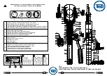
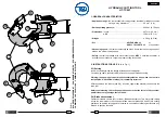
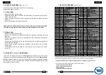
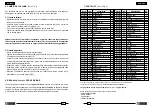
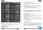
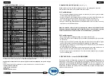
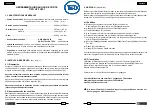
7. PARTS LIST
(Ref. to Fig. 4)
When ordering spare parts always specify the following:
- code number of item
- name of item
- type of tool
- tool serial number.
The items marked
(
★
)
are those
Cembre
recommend replacing if the tool is disassembled.
These items are supplied on request in the “HT-TC051 Spare Parts Package”
The guarantee is void if parts used are not
Cembre
original spares.
Code N°
Item
DESCRIPTION
Qty
Code N°
Item
DESCRIPTION
Qty
25
6