


ENGLISH
HYDRAULIC CUTTING TOOL
HT-TC051
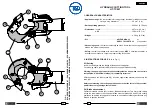
1. GENERAL CHARACTERISTICS
– Application range: the tool is suitable for cutting copper, aluminium or telephone cables
having a max. diameter of ............................. 50 mm (2 in.)
– Rated operating pressure: .......................................................... 600 bar (8,700 psi)
– Dimensions: length .... ................................................................. 497 mm (19.5 in.)
width ........................................................... ............ 129 mm (5.1 in.)
– Weight: .......................................................................................... 4,38 kg (9.6 lbs)
– Oil: ............................................................... AGIP ARNICA 32
or
SHELL TELLUS TX 32
or equivalent
– Advancing speed: the tool automatically switches from a fast advancing speed of
blades to a slower cutting speed.
– Safety: the tool is provided with max pressure valve; MPC 1 special manometer, is
available upon request to check the proper setting of the valve.
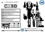
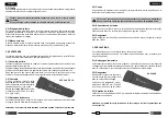
2. INSTRUCTIONS FOR USE
(Ref. to Fig. 1)
2.1) Setting
Insert the cable between the blades at the desired cutting point.
For a running cable, press latch (28) and open the upper blade assembly.
Warning: the opening of upper blade assembly must be done when the tool is in
rest position, with the lower blade (18) completely retracted.
With the cable on the lower blade (18), close the upper blade assembly and secure the
latch (28).
Before commencing the cutting operation ensure that the latch is fully secured:
partial closure may damage the tool head.
2.2) Blade advancement
Operate moveable handle (44) for lower blade advancement. This fi rst stage rapidly
closes the lower blade to the conductor. Make sure that blades (18 and 23) are exactly
positioned on desired cutting point, otherwise re-open blades following instructions as §
2.4 and re-position the cable.
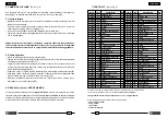
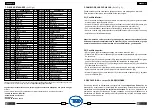
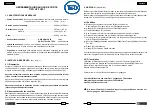
FIG. 3
BLADES REPLACEMENT - CHANGEMENT LAMES - SCHNEIDMESSER
WECHSEL
CAMBIO DE LAS CUCHILLAS - CAMBIO DELLE LAME
28
21
19
20
23
29
24
22
25
18
13
14
26
28
18
29
2