Cembre HT-TC051 Operation And Maintenance Manual Download Page 4

!

ENGLISH

01

02

58

12

03

14

18

13

44

3

28

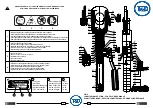
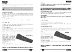
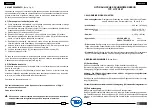
FIG. 2  TOOL POSITION FOR MAINTENANCE OPERATIONS
            POSITION DE L'OUTIL POUR L'ENTRETIEN
           WERKZEUG WARTUNGSPOSITION
            COLOCACION PARA LAS OPERACIONES DE MANTENIMIENTO
  

POSIZIONAMENTO PER LE OPERAZIONI DI MANUTENZIONE   
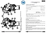
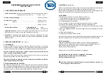
CANVAS BAG

2.3) Cutting

Continue operating the moveable handle, the lower blade advances gradually until the 
cable is fully cut.


T

HE


TOOL


IS


DESIGNED


FOR


CUTTING


COPPER

ALUMINIUM


AND


TELEPHONE


CABLES


DO


NOT


ATTEMPT


TO


CUT


STEEL


OR

 ACSR 

CONDUCTORS

.

2.4) Blade opening

Press the pressure release lever (58) for the rapid retraction of the ram and subsequent 
blade (18) opening.

2.5) Rest setting

After completion of the work, press the release lever (58) to release the oil pressure (refer 
§ 2.4).

3. WARNING

The tool is robust and requires very little daily maintenance. 
Compliance with the following points, should help to maintain the optimum performance 
of the tool:

3.1) Accurate cleaning

Dust, sand and dirt are a danger for any hydraulic device.
Every day, after use, the tool must be cleaned with a clean cloth, taking care to remove 
any residual, especially close to pin and moveable parts.

3.2) Storage


When not in use, the tool should be 
stored and transported in the canvas 
bag, to prevent damage. 
Canvas bag: ref. 010; size  545x160
mm (21.4x6.3 in.); weight 0,15 kg 
(0.33 lbs).

3.3) Head rotation

For ease of operation, the tool head can rotate through 90°.

Warning: do not attempt to turn the head if the hydraulic circuit is pressurised.

Summary of Contents for HT-TC051

Page 1: ...IENUNGSANLEITUNG MANUAL DE USO Y MANTENIMIENTO MANUALE D USO E MANUTENZIONE Cembre Ltd Dunton Park Kingsbury Road Curdworth Sutton Coldfield West Midlands B76 9EB Great Britain Tel 01675 470440 Fax 01675 470220 E mail sales cembre co uk Cembre S p A Via Serenissima 9 25135 Brescia Italia Telefono 030 36921 Telefax 030 3365766 E mail info cembre com Cembre S a r l 22 Avenue Ferdinand de Lesseps 914...

Page 2: ... DO NOT CUT STEEL NE PAS COUPER L ACIER ET L ALMÉLEC KEINEN STAHL SCHNEIDEN NO CORTAR ACERO NON TAGLIARE ACCIAIO 3 TIPO TYPE MAX mm 50 HT TC 051 Made in E U 2 3 1 2 3 Always wear safety glasses and gloves when operating this tool Porter toujours les lunettes de protection et les gants de travail Immer mit Schutzbrille und Handschuhen bedienen Trabajar siempre con las gafas y guantes de seguridad O...

Page 3: ... at the desired cutting point For a running cable press latch 28 and open the upper blade assembly Warning the opening of upper blade assembly must be done when the tool is in rest position with the lower blade 18 completely retracted With the cable on the lower blade 18 close the upper blade assembly and secure the latch 28 Before commencing the cutting operation ensure that the latch is fully se...

Page 4: ...est setting After completion of the work press the release lever 58 to release the oil pressure refer 2 4 3 WARNING The tool is robust and requires very little daily maintenance Compliance with the following points should help to maintain the optimum performance of the tool 3 1 Accurate cleaning Dust sand and dirt are a danger for any hydraulic device Every day after use the tool must be cleaned w...

Page 5: ...f Repeat points d e five times to ensure all air bubbles in the hydraulic circuit are purged into the reservoir g If the oil level is low top up as directed in 4 2 h Remove all air from reservoir 02 and fit cap 01 i Assemble main handle 03 to tool body If the tool continues to malfunction return the tool for service repair as detailed in 6 4 2 Oil top up Every six months check the oil level in the...

Page 6: ...sing the head release the oil pressure and retract the lower blade 18 otherwise the tool head assembly may hit and damage the lower blade 5 2 Upper blade Release latch 28 open the head Remove the circlip 20 and extract the head pin 19 enough to release the tool head assembly Remove circlip 25 and pin 26 to release the latch 28 Remove latch spring from the upper blade Unscrew the 4 screws 21 remove...

Page 7: ...ganciare il dente di arresto 28 e far ruotare il complesso superiore aprendolo comple tamente fino alla battuta Azionare il manico mobile facendo avanzare la lama inferiore 18 fino a mettere in vista il grano di fissaggio 29 sul pistone 14 Con un cacciavite svitare il grano 29 liberando così la lama 18 Togliere la vecchia lama dall apposita sede del pistone inserirvi la nuova e bloccarla con lo st...

Page 8: ...l olio almeno ogni 6 mesi se il livello fosse basso procedere al rabbocco eseguendo le operazioni descritte precedentemente in a b c ed e quindi riempire raso il serbatoio Completare con le operazioni h ed i Usare esclusivamente olio del tipo consigliato al 1 Mai usare olio rigenerato o usato E necessario che l olio sia pulito In occasione di eventuali sostituzioni dell olio smaltire l olio esaust...

Page 9: ...x160 mm 21 4x6 3 in e pesa 0 15 kg 0 33 lbs 3 3 Rotazione della testa La testa dell utensile può ruotare di 90 rispetto al corpo permettendo così all operatore di esguire il lavoro nella posizione più agevole Attenzione non forzare la testa tentando di ruotarla quando l utensile è in pressione ITALIANO FRANÇAIS 23 8 SACCA DI TELA SACOCHE 2 3 Coupe En poursuivant la manœuvre du bras mobile la lame ...

Page 10: ...seul problème nécessitant une intervention qui peut parfois être rencontré est la pré sence d une bulle d air dans le circuit hydraulique Cet incident est caractérisé par un mauvais fonctionnement de l outil au cours de la montée en pression soit la lame inférieure ne monte pas soit elle progresse très lentement soit elle avance par à coups Dans ce cas procéder de la façon suivante 4 1 Elimination...

Page 11: ...empre los elementos siguientes número de código del elemento designación del elemento tipo de herramienta número de serie de la herramienta La garantía pierde eficacia si se utilizan piezas de repuesto distintas de las originales Cembre 6800040 01 TAPON DEPOSITO ACEITE 1 6720050 02 DEPOSITO ACEITE 1 6480055 03 MANGO FIJO 1 6360250 04 JUNTA DE GOMA 1 6740100 05 BOLA 5 32 1 6520160 06 MUELLE DE SUCC...

Page 12: ... alojamiento Destornillar los 4 tornillos 21 y quitar las guías de la izquierda 22 y de la derecha 24 liberando la cuchilla 23 En la cuchilla nueva montar las guías de la izquierda y de la derecha introducir en el asiento de ésta el muelle y volver a montar el diente de retención 28 Montar el grupo superior en la cabeza 13 meter a fondo el pasador 19 y sujetarlo con el aro elástico 20 6 DEVOLUCION...

Page 13: ...festa con un funcionamiento anormal de la herra mienta al bombear el pistón no avanza o bien se mueve muy lentamente ó vibra En este caso se debe actuar del modo siguiente 4 1 Para expulsar las burbujas de aire a Fije la herramienta verticalmente con la cabeza hacia abajo manteniendo el mango móvil 44 separado completamente ver Fig 2 b Desenrosque el mango fijo 03 del cuerpo 12 y sáquelo deslizánd...

Page 14: ...TELA 2 3 Corte Continuando accionando el mango móvil se conseguirá un avance gradual y progresivo de la cuchilla inferior hasta cortar completamente el cable ESTA HERRAMIENTA HA SIDO CONCEBIDA ESPECÍFICAMENTE PARA CORTAR CABLES DE COBRE DE ALUMINIO O PARA TELECOMUNICACIONES NO EMPLEARLA BAJO NINGÚN CONCEPTO CON CABLES DE ACERO O DE ALUMINIO ACERO 2 4 Reapertura de las cuchillas Presionando la pala...

Page 15: ...cuchillas se encuentran exactamente enfrente del punto que se quiere cortar de no ser así volverlas a abrir véase punto 2 4 y volverlas a colocar 4 WARTUNG Siehe Bild 2 Befindet sich Luft im Hydrauliksystem kann es zum fehlerhaftenArbeiten des Werkzeuges kommen Dies zeigt sich in ungewöhnlichem Verhalten des Werkzeuges Bei Pumpbeginn bewegt sich das untere Schneidmesser nicht oder nur sehr langsam...

Page 16: ...3 demontieren Die linke und rechte Führung auf das neue Schneidmesser montieren die Feder in den Sitz einpassen und die Verriegelung 28 erneut montieren Das Schneidmesser auf dem Werkzeugkopf 13 befestigen und den Bolzen 19 mit dem Federring 20 sichern 6 EINSCHICKEN AN Cembre ZUR ÜBERPRÜFUNG Sollten am Gerät Fehler auftauchen wenden Sie sich bitte an unsere Gebietsvertretung welche Sie gerne berat...

Reviews: