


6362020
★
37
JOINT
1
6620090 38
PISTON DE POMPAGE
1
6360240
★
39
JOINT
1
6340590 40
AXE DE BILLE
1
6520200
★
41 RESSORT
1
6740020
★
42 BILLE 1/4" 1
6232000 43
ETIQUETTE (TG. 0351) 1
6480197 44
BRAS MOBILE 1
6380200 45
POIGNEE 1
6895020 46
VALVE DE SURPRESSION
1
6040080
★
47
ANNEAU TEFLON 1
6360140
★
48 JOINT
1
6020027 49
PISTON DE DECOMPRESSION
1
6600020
50
AXE DE RAPPEL LEVIER
1
6520280
★
51 RESSORT
1
6360120
★
52
JOINT
1
6740120
★
53
BILLE 7/32"
1
6600100
54
SUPPORT DE BILLE
1
6520520
★
55 RESSORT
1
6360166
★
56
JOINT
1
6900341
57
VIS M8x10
1
6440100 58
LEVIER DE DECOMPRESSION 1
6760100
59
GOUPILLE ø 3x16 1
6232303 60
PLAQUETTE (TG. 0503) 1
6650118
61
RIVET ø 2,5 x 3,5
2
6635011 62
SOMMET DE DECOMPRESSION
1
6520861 63 RESSORT DE DECOMPRESSION
1
6340720 64
GOUPILLE DE DECOMPRESSION 1
6520160
★
65
RESSORT 1
6740100
★
66
BILLE 5/32" 1
6641020
★
67
RONDELLE DE CUIVRE M6 1
6900601 68
VIS DE ASPIRATION
1
6860131
●
TETE COMPLETE
6780271
▲
PISTON COMPLET
6000088
★
PAQUET RECHANGE
FRANÇAIS
ESPAÑOL
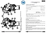
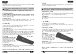
5. CAMBIO DE LAS CUCHILLAS
(Ref. a Fig. 3)
Puede suceder que las cuchillas se estropeen tras un uso prolongado o impropio.
Para efectuar el cambio de las cuchillas, actúe como sigue:
5.1) Cuchilla inferior:
– Abrir la cabeza desenganchando el diente de retención (28) y hacer girar completa-
mente el grupo superior, hasta el tope.
– Accionar el mango móvil (44) para hacer avanzar la cuchilla inferior (18) hasta que
quede visible el tornillo de sujección (29) de la misma sobre el pistón (14).
– Con un destornillador, desenroscar el tornillo (29) y soltar así la cuchilla (18).
– Sacar la cuchilla vieja del alojamiento correspondiente del pistón, colocar la nueva y
sujetarla con el tornillo mencionado.
Atención: antes de volver a cerrar el grupo superior, evacuar la presión del aceite
haciendo retroceder completamente la cuchilla (18); en caso contrario, el grupo
superior podría chocar contra la arista de la cuchilla inferior y estropearla.
5.2) Cuchilla superior:
– Abrir el grupo superior desenganchando el diente de retención (28).
– Quitar el aro (20), extraer el pasador (19) para soltar completamente el grupo superior
de la cabeza.
– Quitar el aro (25), extraer el pasador (26) y separar el diente de retención (28) del grupo
superior. Recuperar el muelle que quedará así liberado de su alojamiento.
– Destornillar los 4 tornillos (21) y quitar las guías de la izquierda (22) y de la derecha
(24) liberando la cuchilla (23).
– En la cuchilla nueva montar las guías de la izquierda y de la derecha, introducir en el
asiento de ésta el muelle y volver a montar el diente de retención (28).
– Montar el grupo superior en la cabeza (13), meter a fondo el pasador (19) y sujetarlo
con el aro elástico (20).
6. DEVOLUCION A
Cembre
PARA REVISIONES
En caso de fallo de la herramienta, contactar con nuestro Agente de Zona quien les
aconsejará y eventualmente les facilitará las instrucciones necesarias para remitir la
herramienta a nuestro centro de servicio mas cercano. En tal caso, adjuntar de ser
posible una copia del Certifi cado de Ensayo entregado en su día por
Cembre
con la
herramienta o a falta de otro elemento de referencia indicar la fecha de compra aproxi-
mada y el número de serie.
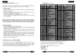
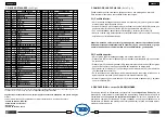
Les éléments accompagnés d’un (
★
) sont ceux que
Cembre
recommande de remplacer en cas de démontage de l’outil.
Ces éléments sont fournis sur demande dans le “Paquet Rechange pour HT-TC051.
Lors de la commande de pièces détachées, prière d'indiquer toujours les éléments suivants:
- numéro de code de l'élément
- dénomination de l'élément
- type d'outil
- numéro de série de l'outil.
La garantie perd tout effet en cas d'emploi de pièces détachées différentes des pièces d'origine
Cembre
.
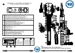
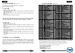
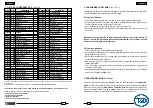
7. PIECES DETACHEES
(Voir Fig. 4)
6800040 01
CAPUCHON DE RESERVOIR
1
6720050
02 RESERVOIR
1
6480055 03
BRAS PRINCIPAL
1
6360250
★
04 JOINT
1
6740100
★
05
BILLE 5/32" 1
6520160
★
06
RESSORT 1
6740020
★
07 BILLE 1/4" 1
6520200
★
08 RESSORT
1
6340590 09
AXE DE BILLE
1
6360270
★
10
▲
JOINT
1
6040181
★
11
▲
ANNEAU TEFLON
1
6160027
12
CORPS
1
6860101 13 TETE
1
6620171 14
▲
PISTON 1
6361810
★
15
▲
JOINT
1
6641020
★
16
▲
RONDELLE DE CUIVRE M6
1
6900334
17
▲
VIS M6x30
1
6420231 18 LAME INFERIEURE
1
6560691 19
AXE DE LAME SUPERIEUR
1
6040421
20 ANNEAU
ELASTIQUE
Ø 10
1
6900315 21
●
VIS M 6x16
4
6370141 22
●
GUIDE LAME INFERIEUR GAUCHE 1
6420241 23
●
LAME SUPERIEURE 1
6370151 24
●
GUIDE LAME INFERIEUR DROIT 1
6700140
★
25
●
ANNEAU ELASTIQUE
1
6560701 26
●
AXE DE LOQUET
1
6520460 27
●
RESSORT 1
6200051 28
●
LOQUET 1
6370250
29 VIS DE FIXATION LAME INFERIEURE 1
6080051 30
▲
ANNEAU GUIDE PISTON
1
6522314 31
▲
RESSORT
1
6360266
★
32
JOINT
1
6360161
★
33
JOINT
1
6560262 34
AXE BRAS MOBILE
2
6700060
★
35
ANNEAU ELASTIQUE
4
6040101
★
36 ANNEAU TEFLON
1
N° Code Elément
DENOMINATION
Q.té
N° Code Elément
DENOMINATION
Q.té
11
20