8
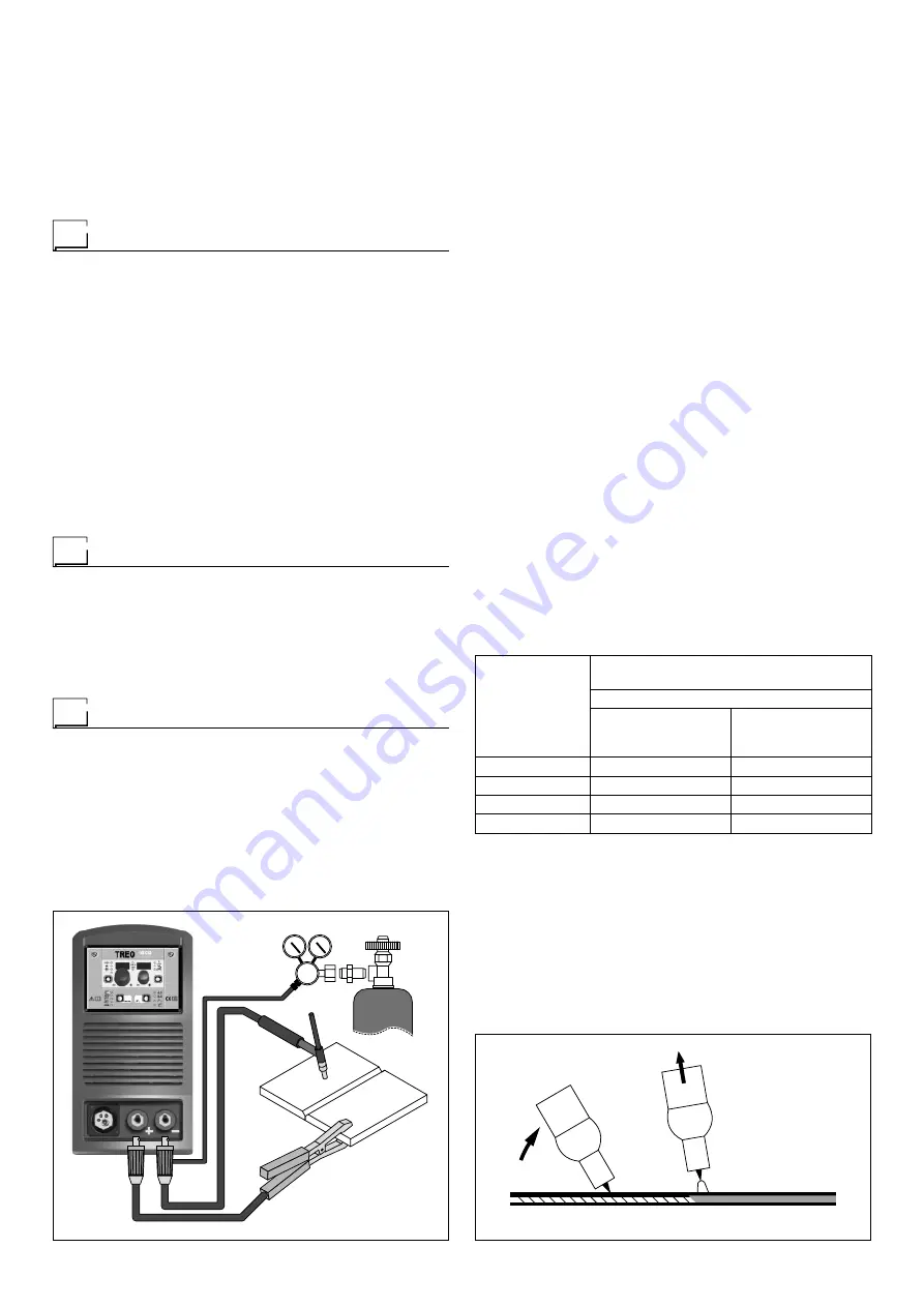
FIG. F
To begin spot welding:
• Place the gas guiding nozzle perpendicular on the workpiece
to be spot welded.
• Press the torch button to start the welding current and wire
feed.
• When the spot welding time expires (SPOT WELD TIME),
the wire feed stops automatically.
• When the torch button is pushed again a new welding cy-
cle starts.
• Release the torch button.
Interval welding (Stitch)
The substantial differences with the spot welding mainly con-
cern the adjustments that must be carried on the welding ma-
chine.
Use the control panel to select the interval welding mode and
then make the changes to the related “Special functions - Fx”
(for further information see the TX control panel manual), which
allows the machine to do this specific type of welding.
To begin interval welding:
• Press the torch button to start the welding current and wire
feed.
• At this point the welding machine automatically carries out
a succession of welded portions (STITCH WELD TIME) fol-
lowed by a pause (STITCH WELD PAUSE), according to the
times entered previously. This procedure stops automatically
only when the TORCH BUTTON is released.
• When the torch button is pushed again the torch begins a
new interval welding cycle.
Aluminium welding
To weld with aluminum wire proceed as follows:
• Replace the drive roller with the appropriate for aluminum
wire.
• Use a torch with a 3m cable and a carbon Teflon sheath.
• Set the pressure between the drive rollers at the minimum,
by turning the screw provided.
• Use argon gas at a pressure of 1,3 - 1,7 bar.
TIG welding with “Lift”
In the TIG process welding is achieved by melting the two metal
pieces to be joined, with the possible addition of material from
the outside, using an arc ignited by a tungsten electrode. The
“Lift” (TCS) type ignition used in TREO equipments makes it
possible to reduce tungsten inclusions on ignition to a mini-
mum. The molten bath and the electrode are protected by and
inert gas (for example, Argon). This type of welding is used
to weld thin sheet metal or when elevated quality is required.
1) Connecting the welding cables (Fig. F):
• Connect one end of the gas hose to the gas connecter on
the TIG torch and the other end to the pressure reducer
on the inert gas cylinder (Argon or similar).
• With the machine switched off:
- Connect the ground cable to the snap-on connector
(positive).
- Connect the relative ground clamp to the workpiece or
to the workpiece support in an area free of rust, paint,
grease, etc..
- Connect the TIG torch power cable to the snap-on con-
nector marked - (negative).
2) Switch the welding machine on by moving the power sup-
ply switch to
I
(Pos. 5, Fig. A).
3) Make the adjustments and do the parameter settings on
the control panel (for further information see the TX con-
trol panel manual).
4) Open the gas cylinder and regulate the flow by adjusting
the valve on the TIG torch by hand.
5) Ignite the electric arc by contact, using a decisive, quick
movement without dragging the tungsten electrode on the
piece to be welded (“Lift” type ignition - Fig. G).
6) The welder has a SWS “Smart Welding Stop” system for
the end of TIG welding. Lifting up the torch without switch-
ing off the arc will introduce a slope down and it will switch
off automatically.
7) When you have finished welding remember to shut the
valve on the gas cylinder.
Table 3 shows the currents to use with the respective elec-
trodes for TIG DC welding. This input is not absolute but is for
your guidance only; read the electrode manufacturers’ instruc-
tions for a specific choice. The diameter of the electrode to use
is directly proportional to the current being used for welding.
Table 3
Ø ELECTRODE
(mm)
ELECTRODE TYPE
Current adjustment field (A)
TIG DC
Tungsten
Ce 1%
Grey
Tungsten
Rare ground 2%
Turchoise
1
10-50
10-50
1,6
50-80
50-80
2,4
80-150
80-150
3,2
150-250
150-250
FIG. G
2000HA86
Summary of Contents for TREO 1800 Synergic MIG-MAG
Page 12: ...12 Electro topographical diagram 2101AB10...
Page 14: ......
Page 22: ......
Page 42: ......


