BG
BD
BMI
D’ C’
B’ A’
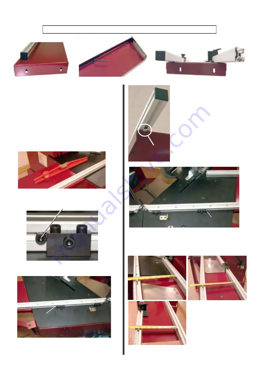
Using a 4-mm Allen key, slightly loosen the locking screws on stops BD and BG located beolw each table
extension. This allows stops BD and BG to slide along them.
Position the left extension support bracket
below the left table.
Slide stop BG of the left extension into
screws 1-2-3 and the 2 rule supports R of the
left table.
Screw the extension to the frame (at C’ and
D’) using screws C and D. Secure the
cylindrical support of the bracket using
screw E.
Set the extension level with the cutting table.
Position the right table support
bracket below the right extension.
Slide right extension stop BD into
screws 1-2-3 of the right table and
the screws of the 2 rule supports
until it is stopped by screws R and
B’.
Screw the extension to the frame
(at A’ and B’) using screws A and
B. Secure the cylindrical support
of the bracket using screw F.
Tighten screws 1,2,3 and the rule
support screws. Set level.
Slide stop BG fully home through screws 1,2,3
and the screws of the 2 rule supports, until it is
stopped by screw B.
R
Measure the distance (1) between stops BD and BMI
and (2) set the same distance at the middle of the exten-
sion, by adjusting BD. Tighten the screw on the
underside. (3) Repeat the operation at the end of BD.
Once the stop spacing is
set, retighten the remaining
screws below the table.
1
2
3
BG
Retighten the locking screws below the table
extension.
B
BD
BD
BMI
Do not loosen the screws of the internal measuring stop BMI (factory setting).
Using the 4-mm Allen key, tighten screws 1,2,3
and the screws of the 2 rule supports.
B’
5
Summary of Contents for CS 960
Page 4: ...C...


