Installation Instructions
NOTE:
Read the entire instruction manual before starting the installation.
Safety considerations
Improper installation, adjustment, alteration, service, maintenance, or
use can cause explosion, fire, electrical shock, or other conditions which
may cause death, personal injury, or property damage. Consult a
qualified installer, service agency, or your distributor or branch for
information or assistance. The qualified installer or agency must use
factory-authorized kits or accessories when modifying this product.
Refer to the individual instructions packaged with the kits or accessories
when installing.
Follow all safety codes. Wear safety glasses, protective clothing, and
work gloves. Have a fire extinguisher available. Read these instructions
thoroughly and follow all warnings or cautions included in literature and
attached to the unit. Consult local building codes, the current editions of
the National Fuel Gas Code (NFGC) NFPA 54/ANSI Z223.1 and the
National Electrical Code (NEC) NFPA 70.
In Canada, refer to the current editions of the National Standards of
Canada CAN/CSA-B149.1 and .2 Natural Gas and Propane Installation
Codes, and Canadian Electrical Code CSA C22.1.
Recognize safety information. This is the safety-alert symbol
. When
you see this symbol on the unit and in instructions or manuals, be alert to
the potential for personal injury.
Understand the signal words DANGER, WARNING, and CAUTION.
These words are used with the safety-alert symbol. DANGER identifies
the most serious hazards which will result in severe personal injury or
death. WARNING signifies hazards which could result in personal
injury or death. CAUTION is used to identify unsafe practices which
may result in minor personal injury or product and property damage.
NOTE and NOTICE are used to highlight suggestions which will result
in enhanced installation, reliability, or operation.
Special Venting Requirements for Installations in
Canada
Installation in Canada must conform to the requirements of CSA B149
code. Vent systems must be composed of pipe, fittings, cements, and
primers listed to ULC S636. The special vent fittings, accessory
concentric vent termination kits, and accessory external drain trap have
been certified to ULC S636 for use with those Royal Pipe and IPEX
PVC vent components which have been certified to this standard. In
Canada, the primer and cement must be of the same manufacturer as the
vent system – GVS-65 Primer (Purple) for Royal Pipe or IPEX System
636, PVC/CPVC Primer, Purple Violet for Flue Gas Venting and
GVS-65 PVC Solvent Cement for Royal Pipe or IPEX System 636(1)t,
PVC Cement for Flue Gas Venting, rated Class IIA, 65 deg C. must be
used with this venting system - do not mix primers and cements from
one manufacturer with a vent system from a different manufacturer.
Follow the manufacturer’s instructions in the use of primer and cement
and never use primer or cement beyond its expiration date.
The safe operation, as defined by ULC S636, of the vent system is based
on following these installation instructions, the vent system
manufacturer’s installation instructions, and proper use of primer and
cement. All fire stop and roof flashing used with this system must be UL
listed material. Acceptability under Canadian standard CAN/CSA B149
is dependent upon full compliance with all installation instructions.
Under this standard, it is recommended that the vent system be checked
once a year by qualified service personnel.
The authority having jurisdiction (gas inspection authority, municipal
building department, fire department, etc) should be consulted before
installation to determine the need to obtain a permit.
*IPEX System 636™ is a trademark of IPEX Inc.
Consignes spéciales pour l’installation de
ventilation au Canada
L’installation faite au Canada doit se conformer aux exigences du code
CAN/CSA B149-2010. Ce systême de ventillation doit se composer de
tuyaux, raccords, ciments et apprêts conformes au ULC S636. La
tuyauterie de ventilation des gaz, ses accessoires, le terminal
concentrique mural ainsi que l’ensemble du drain de condensation
extérieur fourni par le fabricant de cette fournaise ont été certifiés ULC
S636 pour l’application des composantes Royal Pipe, IPEX PVC qui
sont certifiées à ce standard. Au Canada, l’apprêt et le ciment doivent
être du même fabricant que le système d’évacuation. L’apprêt GVS-65
(Purple) et le ciment-solvant GVS-65 doivent être utilisé avec les Royal
Pipe. Système IPEX 636, apprêt PVC/CPVC, Purple pour évacuation
des gaz de combustion et système IPEX 636(1)t, ciment PVC pour
évacuation des gaz de combustion, coté classe IIA, 65 deg C. doivent
être utilisés avec le système d’évacuation IPEX 636 – Ne pas combiner l
’apprêt et le ciment d’un manufacturier avec un système d’évacuation
d’un manufacturier différent.
Bien suivre les indications du manufacturier lors de l’utilisation de
l’apprêt et du ciment et ne pas utiliser ceux-ci si la date d’expiration est
atteinte.
L’opération sécuritaire, tel que définit par ULC S636, du système de
ventilation est basé sur les instructions d’installation suivantes, ainsi que
l’usage approprié de l’apprêt et ciment. Tout arrët feu et solin de toit
utilisés avec ce système doivent être des matériaux listés UL.
L’acceptation du standard Canadien CAN/CSA B149 est directement
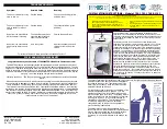
KGAET0201ETK
External Trap Kit
For use with 35 in (889 MM) Condensing Gas Furnaces
WARNING
!
FIRE, EXPLOSION, ELECTRICAL SHOCK HAZARD
Failure to follow this warning could result in personal injury, death
and/or property damage.
The ability to properly perform maintenance on this equipment requires
certain knowledge, mechanical skills, tools, and equipment. If you do
not possess these, do not attempt to perform any maintenance on this
equipment other than those procedures recommended in the Home
Owner’s Information Manual.