


60
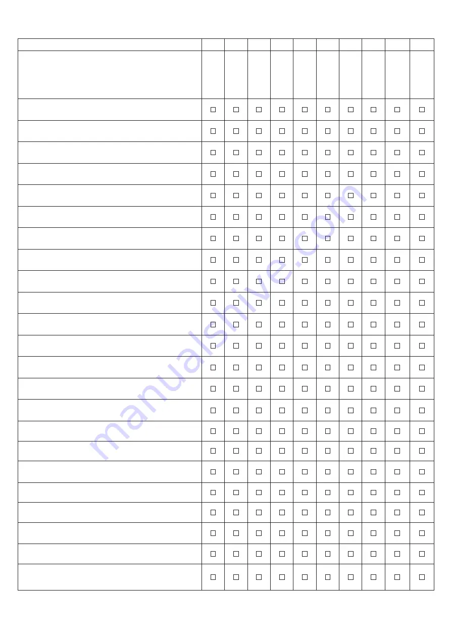
Yearly maintenance program
Year 1
Year 2 Year 3 Year 4 Year 5 Year 6 Year 7 Year 8
Year 9 Year 10
Maintenance date
----/----/----
----/----/----
----/----/----
----/----/----
----/----/----
----/----/----
----/----/----
----/----/----
----/----/----
----/----/----
Disconnect power supply and protect the PC board to ensure it
cannot get wet during service
Using a digital manometer, check incoming gas pressure at the gas
regulator
Using a digital manometer, check pressure at bottom of gas valve
Check gas line size & length, ensuring it is adequately sized
Isolate & drain the boiler, check the expansion tank pressure is
correct for the system
Check that area is free from combustible materials, gasoline, and
other flammable vapors and liquids
Check that the Pressure Relief Valve is properly oriented in a vertical
position beneath the boiler
Check the correct working of the relief valve. Refer to manufacturer’s
instructions on valve
Check the water domestic inlet screen, clean if necessary (BWC
model only)
Check the water inlet filter screen in the inlet manifold, clean if
necessary
Check the flowmeter filter screen, clean if necessary
Check venting type, length, installation, condition & screens
Visually check top of vent for soot. Call service person to clean. Some
sediment at bottom of vent is normal
Clean the screens in the vent terminal
Visually inspect all flue product carrying areas of the boiler including
the venting system and main burner for proper functioning,
deterioration or leakage
Verify that the vent is not obstructed. Check for and remove any
obstruction to the flow of combustion or ventilation air to heater
Venting must be pitched towards the boiler to allow condensate to
drain
Ensure that condensate drains are inspected and ensure that
condensate is being directed to appropriate condensate management
system or drain, as required by local codes
Check operation of safety devices. Refer to manufacturer’s
instructions
Check fan and fan motor for deposits presence and damage
Check if there is any flue leakage from the heat exchanger flue outlet
and adaptors junctions. In case of leakage detection replace the
related gaskets (1).
Remove the burner door (8), check that combustion chamber is free
of deposits and proceed to clean with water and nylon brush
.
Check the burner door insulation panel (6), gasket (4) and high
temperature glass braided rope (5) for deterioration, and if they are
worn, replace them.
Yearly maintenance program
Year 1
Year 2 Year 3 Year 4 Year 5 Year 6 Year 7 Year 8
Year 9 Year 10
Maintenance date
----/----/----
----/----/----
----/----/----
----/----/----
----/----/----
----/----/----
----/----/----
----/----/----
----/----/----
----/----/----
Check the combustion chamber insulation panel (3)and, if it is worn,
replace it.
Check the condition of the burner (7), ensure that it is not loose;
clean if necessary.
Verify spark and check the flame ignition electrode (12) for
deterioration and, if it is worn, replace it.
If the electrode is removed from its seat, its gasket (11) must be
replaced.
Check the flame sensor electrode (10) for deterioration and, at the
slightest sign of deterioration, replace it. If the sensor is removed
from its seat, its gasket (9) must be replaced
.
Check the boiler condensate trap, remove and clean if needed – re-
prime trap
Check the correct working of the condensate check valve dispositive
Refill the boiler and purge all air from system
Check for piping leaks around pumps, relief valves and other fittings.
Repair, if found. DO NOT use petroleum-based stopleak
Inspection of the low water cutoffs in the boiler and system. Also it
needs to specify that float type low water cutoffs must be periodically
flushed.
Power boiler back on
Verify the polarity and ground of the power supply (L-N=120v,
L-G=0v, N-G=0v)
Check incoming power to spark generator - minimum 120VAC
Verify the unit is set for the proper gas by accessing the "Gas Type"
parameter on the boilers front screen
Visually inspect the burner flame and ignition sequence to ensure
proper operation
Perform a combustion check per section 10.21 - Combustion
Analysis in the Installation &
Operation Instructions For Contractors
using a combustion analyzer. Ensure the CO2% and CO ppm are
within the acceptable limits given in the IOM and by local codes.
Ensure the CH and DHW temperature setpoints are set correctly
Door gasket maintenance procedure
Year 1
Year 2 Year 3 Year 4 Year 5 Year 6 Year 7 Year 8
Year 9 Year 10
Maintenance date
----/----/----
----/----/----
----/----/----
----/----/----
----/----/----
----/----/----
----/----/----
----/----/----
----/----/----
----/----/----
Replace the burner door gasket (4).
Gas valve maintenance procedure
Year 1
Year 2 Year 3 Year 4 Year 5 Year 6 Year 7 Year 8 Year 9
Year
10
Maintenance date
----/----/----
----/----/----
----/----/----
----/----/----
----/----/----
----/----/----
----/----/----
----/----/----
----/----/----
----/----/----
Gas valve


