background image

Chilled Water and Drain Piping 

 Facing the

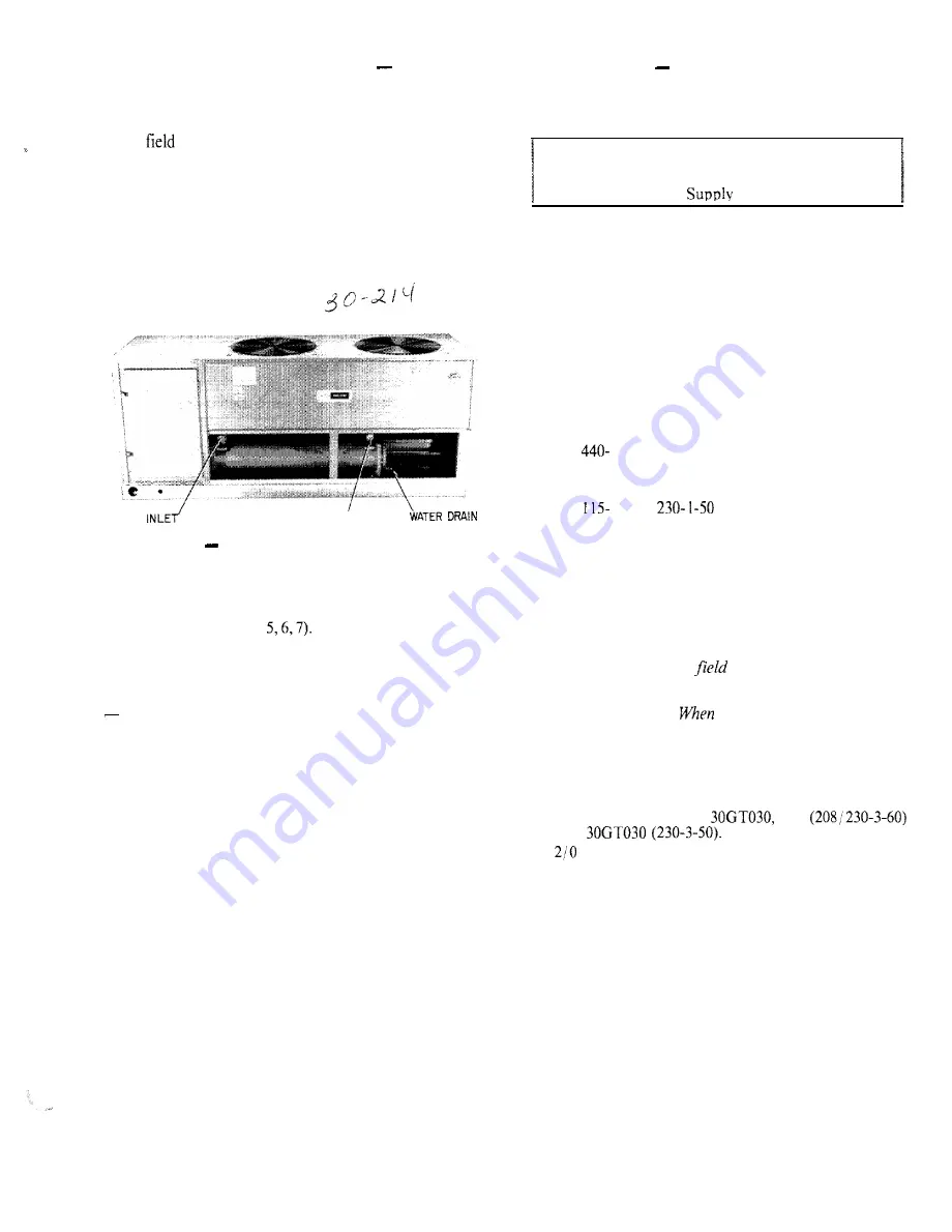
cooler side of the unit, the return water connection is on

the left and the leaving water connection is on the right.
See Fig. 4, 5, 6, 7. A means of venting air from the high
point of the field-installed piping should be provided.
After 

 piping is complete, in area where piping is

exposed to low ambient temperatures (32F or below),
freeze-up protection is recommended using ethylene
glycol or electric heat tapes. Heat tapes should possess a
rating for area ambients and  covered  with a suitable
thickness of closed cell insulation. Route power for
heating tapes from a separate fused disconnect.  Identify
disconnect as heat tape power  source  with warning that
power must not be turned off except when unit is being
serviced.

WATER 

WATER OUTLET’


Fig. 4 

 Water Connection Locations

The cooler drain connection is at the opposite end from

the compressor (see Fig. 

 Insulate the drain piping,

similar to the chilled water piping, for at least one foot
(305 mm) from cooler.

PREPARATION FOR YEAR-ROUND OPERATION

If unit is on year-round operation, add sufficient

ethylene glycol to chilled water to prevent freezing under

operating ambient conditions. Consult local water

authority  on  characteristics of area water and add a

recommended inhibitor to the chilled water.

PREPARATION FOR WINTER SI-IIJTDOWN 


Do

not shut off control power disconnect during off-season

shutdown. 

At end of cooling season, drain water from

system. Replace drain plug and put 2 gallons (8 liters) of
ethylene glycol in cooler to prevent freezing of residual
water. Remove plug on top of leaving chilled water
nozzle to add glycol. At beginning of next chilling
season, refill cooler and add recommended inhibitor.

Power Supply 

 Electrical characteristics of avail-

able power supply must agree with unit nameplate rating.
Supply voltage must be within limits shown in Table 2.

IMPORTANT: Operating unit on improper supply

voltage, or with excessive phase imbalance, con-
stitutes abuse and may affect Carrier warranty. See

Unbalanced  3-Phase 

  Voltage, page 4.

Power Wiring 

 All power wiring must comply with

applicable  local  and national codes. Install field-supplied
branch circuit fused disconnect(s) per NEC (National

Electrical Code, U.S.) of a type that can be locked OFF

or OPEN. Disconnect(s) must be within sight from and
readily accessible from unit in compliance  with  NEC

Article 

 14.

GENERAL WIRING NOTES

1.

2.

3.

4.
5.

6.

The 

 l-60 or 


 control circuit power must be

from a separate source, through a field-supplied fused
disconnect rated at 7 amps.
Crankcase and cooler heaters are wired in the control
circuit so they  are  always operable  as  long as control
power supply disconnect is on, even if any safety
device is open  or unit stop-start switch is off. Heaters
are wired ahead of stop-start switch. They are pro-
tected by 7-amp fuse in control power supply
disconnect.

The control circuit 

 supply disconnect should

never be open except when unit is being serviced or is

to be down for aprotongedperiod in which case cooler

should be drained. 

 operation is resumed, crank-

case heater should be energized for 24 hours before
start-up.

Power entry is at one  end  only.

Maximum field wire sizes allowed by lugs on terminal

block are:

350 

MCM  for  Models 

 035 

and 


 AWG for all other models.

Terminals for field power supply are suitable for
copper, copper-clad aluminum or aluminum con-
ductors. Insulation must be rated 167 F (75 C)
minimum.

Summary of Contents for 30GT 015

Page 1: ...quipment Rigging Preferred method is with spreader bars from above the unit Use Z in 50 mm 0 D pipe or hooks in lifting holes Rig with 4 cables and spreader bars Al1 panels must be in place when riggi...

Page 2: ...see clearance dimensions in Fig 5 6 7 For multiple units allow 8ft separation between units for airflow and service Mounting Unit When unit is in proper location use of mounting holes in base rails is...

Page 3: ...beginning of next chilling season refill cooler and add recommended inhibitor Power Supply Electrical characteristics of avail able power supply must agree with unit nameplate rating Supply voltage mu...

Page 4: ...lled water line to prevent unit from running when water is not circulating through the cooler This switch no HR8 1 LG005 is available as an accessory from Service Parts Center or equivalent can be fie...

Page 5: ...OPER WT Ib AT SUPPORT POINTS 6OHz 1 2 3 4 Tot 0 1 5 5 1 0 3 7 6 4 3 4 3 2 0 1 6 4 0 015C 5 3 9 3 9 7 4 5 8 3 3 8 1 7 3 2 0 2 0 574 1 4 2 3 4 7 4 3 5 0 1821 02OC 6 1 3 451 5 0 7 3 7 4 1945 50 Hz 4 3 9...

Page 6: ...G T O P V I E W AIRFLOW IHRU 5 4 MIN CLEARANCE FOR C O O L E R R E M O V A L WATER OUTLET 2 FPT c OF COOLER NOZZLE5 WAltK UKAIN 4 6 5 8 C23881 7 IO L324 71 J lo 7 13 16 6 5 8 4 SIDE VIEW wing 30GT015...

Page 7: ...0GT030 2 2 6 8 1 0 2 9 30GT030C 2 4 7 4 1 1 2 2 50 HZ NOTE C INDICATES COPPER COIL 1 cl3153 4 3 3 c i APPROX OPER WT Ib AT SU PPORT POINTS HINGED ACCESS b 1 c e i C2353 9 l 4 I 119 11 END VIEW 3 4 DIA...

Page 8: ...I A UPPLY JR TOP VIEW AIRFLOW THRW t 122353 f 7 4 MIN CLEARANCE FOR COOLER REMOVAL a WATER OUTlET 1 8 0 H 1 I I I 1 880 MTG H O L E S i kl Q 7 IO __ f8121 2 7 1S l6 6 S S 8 IO 7 13 1Ei S I D E V I E W...

Page 9: ...CATES COPPER COIL CONTROL BOX 22 23 7 8 D I A FIELD CONTROL CIRCUIT HIRING 63 5 92 13 2 l 2 3 5 B FIELD MAIN PC WER SUPPLY APPROX OPER WT lb AT SUPPORT POINTS HINGED ACCESS DOOR HATER I N L E T 2 l 2...

Page 10: ...OP VIEW IRFLOW THRU ONDENSER FAN No aB 28451 9 4 MIN CLEARANCE FOR COOLER REMOVAL i_ 12584lt 8 5 3 4 4 f1693 6 5 8 t OF COOLER DRAIN El6991 4 2 1 s El1 C44241 14 6 l 8 S I D E V I E W dimensional Draw...

Page 11: ...plied to unit terminals is not below or above listed minimum and maximum timits TAll fans are protected by a single circuit breaker the IRA for the starting compressor plus the total RLA for all runni...

Page 12: ...ment or other equipment to which the chiller supplies liquid Con sult the manufacturer s instructions If used pump auxiliary contactor and flow switch interlocks must be properly installed see Fig 8 T...

Page 13: ...gle switch to START Be sure all safety devices are satisfied Check to see that the leaving chilled water tempera ture agrees with the dial setting on the temperature controller If it is not the same a...

Page 14: ...n moderately without torquing all the flange bolts in the sequence shown Step 2 Repeat Step 1 tightening the bolts to the specified torque JcJ Fig 11 Tightening Sequence Cooler Head Bolts ik l Line So...

Page 15: ...mpressor stops and the liquid line solenoid valve de energizes Manual reset is required to restart The chilled water circulating pump continues to operate during lockout period WINTER SHUTDOWN At the...

Page 16: ...n and allow the unit to run through a cycle At the instant the last step of capacity unloads switch no 1 opens read the tempera ture If it is not the same as the dial reading the variation can be comp...

Page 17: ...gh pressure switch HPS open low water temperature cutout LWTC RESTART The unit recycles and restarts automati cally under Time Guard control when power is restored or when SW is closed or when contact...

Page 18: ...U U05 in 0 I3 mm d Tube ID before rolling use Elliott tube gage 0 549 ip 13 9 mm e S of twice the wall thickness S9 s of b minus d 0 004 in 0 10 mm f Tube ID after rolling g t d e OS in f4 2 mm NOTE...

Page 19: ...l valve 3 Miswired solenoid 4 Weak broken or wrong valve body spring COMPRESSOR WILL NOT LOAD 1 Miswired solenoid 2 Defective capacity control valve 3 Plugged strainer high side 4 Stuck or damaged unl...

Page 20: ...s the right to discontinue or change at any time specifications or designs without notice and without incurring obligations Book 2 I PC111 Catalog No 533 034 Printed in U S A Form 30GT ISI Pg 17 8 88...

Reviews: