


Compressor Protection
BREAKER
Calibrated trip manual reset,
ambient compensated, magnetic breaker protects against
motor overload and locked rotor conditions.
THERMOSTAT
On
compres-
sors, a sensor embedded in motor windings protects
against overtemperature. A sensor in the discharge gas of
compressor reacts to excessively high discharge gas
temperature and shuts off the compressor.
GUARD@ control protects compressor against
short cycling. See Sequence of Control (page 14).
CRANKCASE HEATER minimizes a b s o r p t i o n o f
liquid refrigerant by oil in crankcase during brief or
extended shutdown periods. Source of
60 Hz, or
Hz power is the auxiliary control power,
independent of the main unit power. This assures com-
pressor protection even when main unit power disconnect
switch is off.
IMPORTANT: Never open any switch or dis-
connect that de-energizes the crankcase heater unless
unit is being serviced or is to be shut down for a
prolonged period. After a prolonged
on a
service job, energize the crankcase heater for 24
hours before starting the compressor.
Cooler
Protection
HEATER CABLE
A heater cable is helically wound
around the entire length of the cooler. A thermostat
energizes the cable whenever the ambient temperature is
35 F (1.7 C) or lower. The cable is between the cooler and
the insulation blanket around the cooler. The heater
cable and the insulation protect the cooler down to -20 F
(-29
ambient temperature.
Since the 115-l-60, or 230-I-50 auxiliary power source
for the heater cable is separate from main power source,
power to heater is assured even though the main unit
power may be off.
Do not disconnect heater cable power when servicing
compressor if ambient temperature is below 40 F
(4.4 C). If power to the heater cable is cut off, or if
unit is to be down for a prolonged period, drain
the
SAFETY THERMOSTAT (Freezestat or Low Water
Temperature Cutout)
The sensing bulb is located in the
cooler nozzle at the chilled water end. To remove the
sensing bulb, loosen the setscrew at the top of well and
pull the bulb out. Before replacing the bulb, half fill the
well with heat conductive compound (multi-service
grease for high or low humidity conditions can be used).
Then insert the bulb entirely into the well and tighten the
setscrew.
the split
is in the well recess.
The thermostat is factory set to open at 36 2 F (2.2
1.1
It opens and locks out the compressor safety
circuit. The compressor stops and the liquid line solenoid
valve de-energizes. Manual reset is required to restart.
The
water circulating pump continues to operate
during lockout period.
WINTER SHUTDOWN
At the end of the
season, drain the water from the
(see drain loca-
tion in Fig. 5, 6, 7). Replace the drain plug and put 2
gallons (8 L) of ethylene glycol in the cooler to prevent
any residual water in the cooler from freezing. At the
beginning of the next cooling season, refill the cooler and
add the recommended inhibitor.
High-Pressure Switch
has fixed, nonadjustable
settings. Switch is mounted on the compressor.
TO CHECK
Open the condenser fan circuit breaker. Head pressure
builds up until compressor shuts down. This should be at
the cutout pressure in Table 3. Close condenser fan circuit
breaker. After pressure drops to cut-in setting, reset
control circuit by opening, then closing the control cir-
cuit switch. After control circuit is reset, the Time Guard@
timer cycles and in approximately 5.5 minutes the com-
pressor restarts.
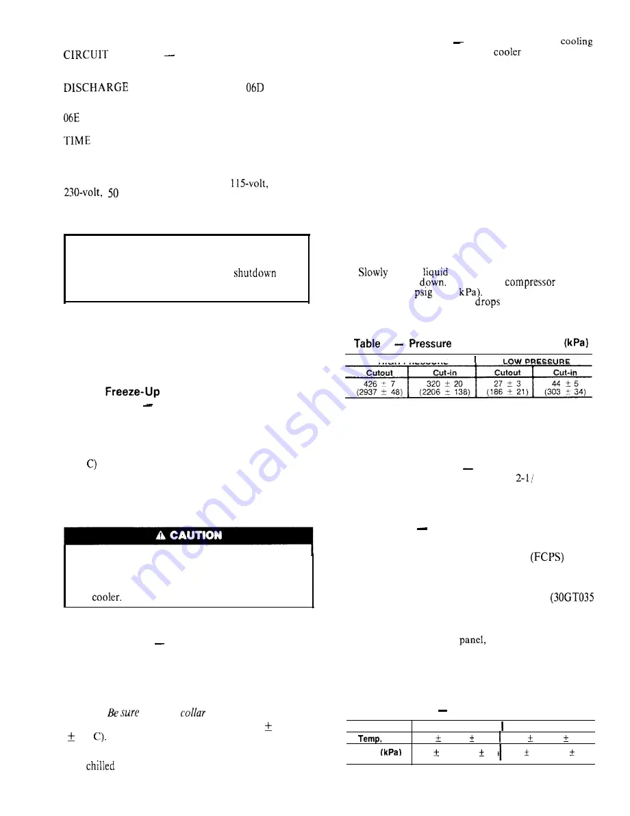
Low-Pressure Switch
has fixed, nonadjustable
settings.
Switch is mounted on the compressor.
TO CHECK
close
shutoff valve and allow com-
pressor to pump
Do not allow
to pump
down below 2
(13.8
Compressor should shut
down when suction pressure
to cutout pressure in
Table 3, and should restart when pressure builds up to
cut-in pressure shown.
3
Switch Settings,
psig
HIGH PRESSURE
Winter Start Control
Switch D in the 4-function
timer bypasses low-pressure switch for
2 minutes on
unit start-up.
Head Pressure Control
reduces condensing capacity
under low ambient temperature conditions.
FAN CYCLING
These 30GT units have standard pro-
vision for fully automatic intermediate-season head
pressure control through condenser fan cycling. Fan no. 2
is cycled by a fan cycling pressure switch
which
responds to variation in discharge pressure. The pressure
sensor is located in the liquid line of the refrigerant circuit.
Fan no. 3 cycling is controlled by outdoor air temperature
through an air temperature switch (ATS)
units only).
The ATS is located in the lower divider panel between
the compressor compartment and condenser section.
Through a hole in the
the sensing element is
exposed to air entering the no. 1 fan compartment. Fan
no. 1 is non-cycling. Table 4 shows the operating set-
tings of the fan cycling pressure switch and the air tem-
perature switch.
Table 4
Fan Cycling Controls
CONTROL BY
S W I T C H O P E N S S W I T C H C L O S E S
F (C)
7 0
3 (21
1.7)
8 0
3 ( 2 7
1.7)
Pressure,
osia
1 6 0
1 0 (1103
69) 2 6 0
15 ( 1 7 9 3
103)
NOTE: See Fig. 5, 6, 7 for fan arrangement.
1 2


