


30
NRG User Manual | © 2020 | CARLO GAVAZZI LTD.
V1.0 | NRG EtherCAT User Manual | © 2022 | CARLO GAVAZZI LTD.
EN
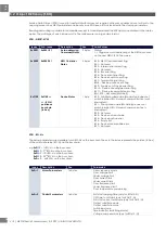
7.4
Alarms – RG..N
SSR Overtemperature
Description
This situation happens when the RG..N does not operate within the rated
specifications causing the SSR to overheat. The output of the RG..N is switched OFF
to prevent the RG..N from getting damaged due to overheating. When the RG..N
cools down, the alarm automatically recovers unless alarm latching is selected, the
Alarm LED is switched OFF, and the RG..N output can be switched accordingly
Diagnose
Confirm that RG..N used is operated within the rated specifications (current rating,
spacing and surrounding temperature).
SSR Overtemperature Pre-warning
Description
This is not an alarm condition and has no effect on the function of the RG..N. The
Over-Temperature Pre-warning alarm is activated when the pre-warning margin
set on the RG..N is not respected. For example, the over temperature prewarning
has been set to 40degC and the actual delta is 39degC. In this case, the over
temperature prewarning alarm is activated. This alarm is re-set when the actual
temperature reading is ≥ 40degC. This alar
m does not trigger the Alarm LED on the
RG..Ns.
Diagnose
Confirm that RG..N used is operated within the rated specifications (current rating,
spacing and surrounding temperature).
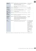
Load deviation alarm
Description
This alarm works in conjunction with the TEACH Voltage Reference, TEACH Current
Reference and TEACH % load deviation settings. If the values of the TEACH Voltage
and Current reference are > 0 either through a ‘TEACH’ command or updated
manually; the load deviation alarm is activated.
With a TEACH command the values of Vref and Iref registers will be updated by
measuring the present current and voltage over a period of time. The TEACH
command is refuted in case of alarms present on the system. If the TEACH is
unsuccessful, the values of Vref and Iref will be cleared to 0. The TEACH command
does not take control of the output of the SSR, it is up to the user to issue a TEACH
command when the output is switched ON with a control percentage of >5%. The
duration of the TEACH procedure shall take up to a maximum of 35s depending on
the level of control percentage. A ‘Store Permanently’ command is required after
a TEACH command for the values of the Vref and Iref to be saved permanently in
the device for next power up.
The load deviation alarm is issued when a change in resistance > the % load
deviation setting is detected. The resistance is measured using the Voltage and
Current reference. The load deviation alarm is useful to detect changes in the load
either due to load degradation or partial load failure when more than one load is
connected to the SSR.
Diagnose
Check loads for degradation or partial load failure (in case of multiple loads with 1
RGx1A..N). Take into consideration the load thermal coefficient when setting the
percentage deviation in LDEVPR to avoid this alarm from being issued
unnecessarily.
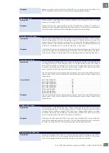
Mains loss
Description
Voltage and current signals are missing for more than 3 mains half cycles. The
cause is a mains loss (Ref terminal must be connected to identify this alarm
otherwise alarm can be either mains loss or load loss)
Diagnose
Ensure mains supply is ON. Confirm that protection (fuses / miniature circuit
breakers) have not tripped. Ensure L1 terminal of RG..N is properly connected.
Load loss / SSR Open Circuit
Description
Load is not switching ON for > a mains half cycle when control signal is present. The
cause is either a load loss or a RG..N open circuit condition.


